Preparation mould and method of ceramic-based corrugated wing air inlet leading-edge panel

A technology of an air inlet and a leading edge plate, which is applied to the preparation mold and field of a leading edge plate of an air inlet of a ceramic-based corrugated airfoil, can solve the problem of small space utilization, poor heat insulation effect of a solid plate, and increased front air intake. Edge quality and other issues to achieve the effect of improving the overall performance

Active Publication Date: 2015-06-24
HARBIN UNIV OF SCI & TECH
View PDF8 Cites 2 Cited by
  • Summary
  • Abstract
  • Description
  • Claims
  • Application Information

AI Technical Summary

Problems solved by technology

[0004] The purpose of the present invention is to provide a preparation mold and method for the leading edge plate of the air inlet of a ceramic base corrugated wing, to solve the problem that the leading edge plate of the air inle

Method used


Image

  • Preparation mould and method of ceramic-based corrugated wing air inlet leading-edge panel
  • Preparation mould and method of ceramic-based corrugated wing air inlet leading-edge panel
  • Preparation mould and method of ceramic-based corrugated wing air inlet leading-edge panel

Examples


Example Embodiment

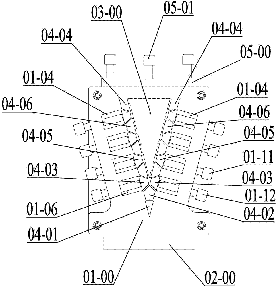
[0031] Specific implementation mode one: combine Figure 1 to Figure 15 Explain that the mold in this embodiment includes a concave block 02-00, a convex block 03-00, a convex block pressing plate 05-00, a triangular long block 04-01, a pentagonal long block 04-02, and two main bodies Plate 01-00, two trapezoidal strips with missing corners 04-03, two end trapezoidal strips 04-04 and two trapezoidal strip groups,

[0032] The top surface of the concave block 02-00 is provided with a triangular through groove 02-01 along the horizontal direction, and the shape of the convex block 03-00 is consistent with the shape of the triangular through groove 02-01 and placed in the triangular through groove 02-01.

[0033] The two main boards 01-00 are arranged vertically opposite to each other at both ends of the triangular through slot 02-01, and the two main boards 01-00 are detachably fixed by several threaded connectors.

[0034] The triangular strip 04-01 and the pentagon strip 04-02 ...

Example Embodiment

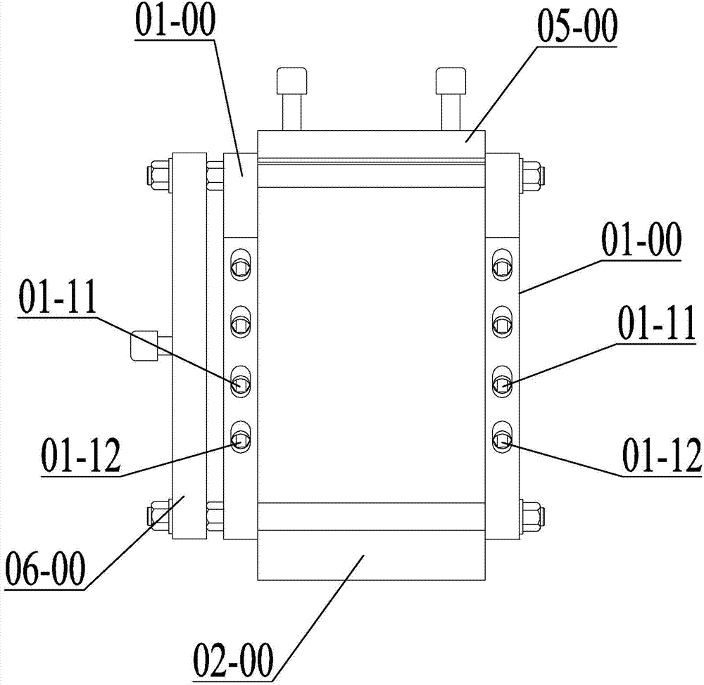
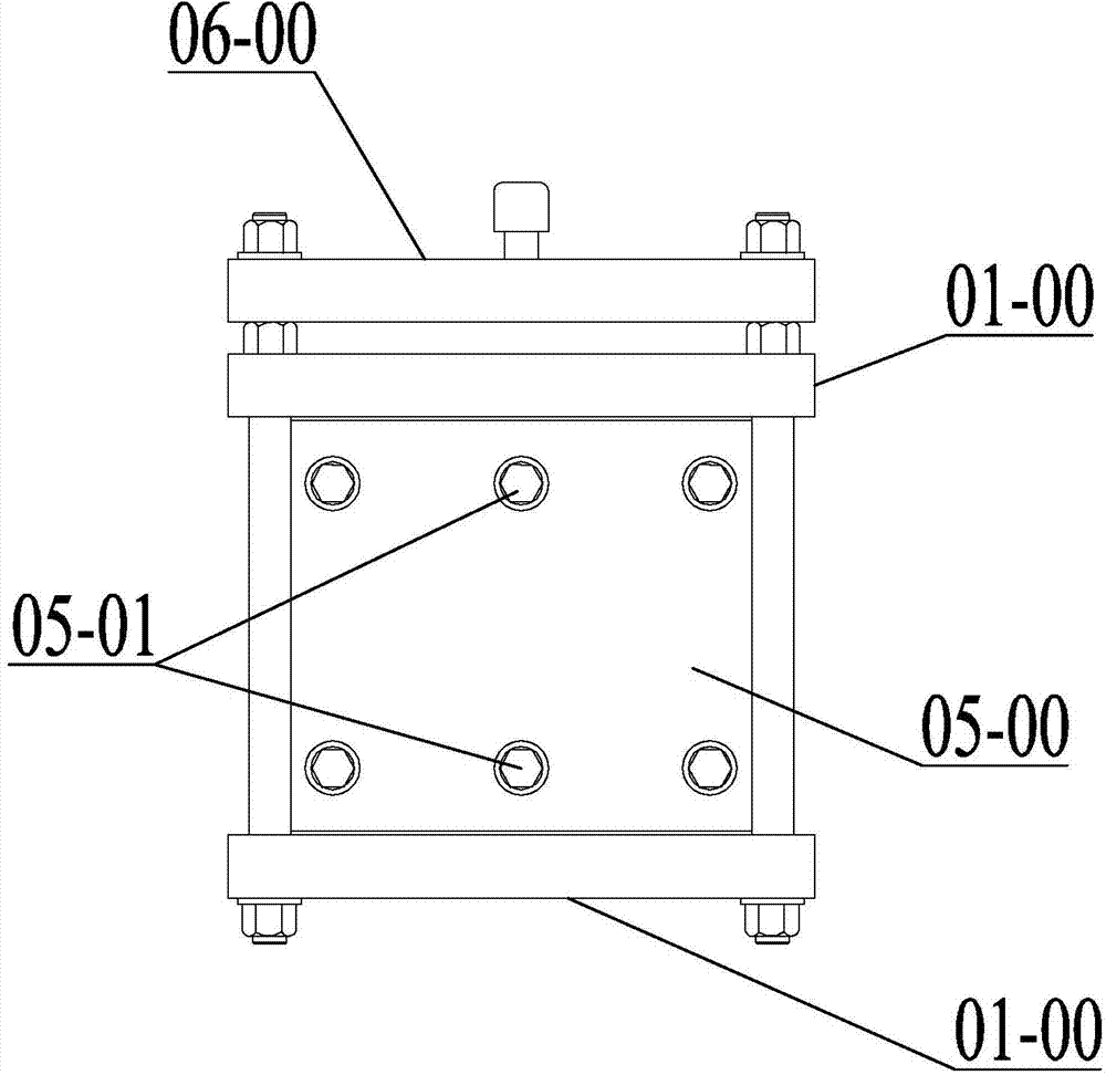
[0051] Specific implementation mode two: combination Figure 1 to Figure 15 Note that the mold in this embodiment also includes dismantling the strip plate 06-00. It is detachably connected to the main body plate 01-00 through threaded connectors, and the surface of the strip plate 06-00 is provided with several fourth threaded through holes 06-01, and several fourth threaded through holes 06 The arrangement of -01 is the same as that of the triangular through-hole 01-01, pentagonal through-hole 01-02, two trapezoidal through-holes with missing corners 01-07, and two trapezoidal through-holes at the end 01-01- 08. The arrangement of the first trapezoidal through holes 01-03 and the second trapezoidal through holes 01-05 is consistent, and each fourth bolt is screwed into a fourth threaded through hole 06-01.

[0052] All the strips can be removed smoothly and the disassembly speed of the strips can be improved by using the dismantling strip plate 06-00. During the use of the ...

Example Embodiment

[0054] Specific implementation mode three: combination Figure 1 to Figure 15 Note that the moving trapezoidal strips 04-05, the missing corner trapezoidal strips 04-03 and the fixed trapezoidal strips 04-06 in this embodiment are all isosceles trapezoidal strips with the same shape, and the isosceles trapezoidal length The included angle between the waist plane of the bar and the lower bottom plane is 10 degrees to 75 degrees, and the waist plane of any adjacent moving trapezoidal long bar 04-05 and the fixed trapezoidal long bar 04-06 are set relatively parallel, and the trapezoid with missing corners The waist planes of the elongated blocks 04-03 and the adjacent fixed trapezoidal elongated blocks 04-06 on the same side are relatively parallel to each other.

[0055] The undisclosed technical features in this embodiment are the same as those in the second embodiment.


PUM


Abstract

The invention relates to a preparation mould and a method of a ceramic-based corrugated wing air inlet leading-edge panel, and aims at solving the problem that the existing air inlet leading-edge panels of the existing airplanes are V-shaped solid panels so that the weight of the air inlet leading edges is increased, the thermal insulation effect of the solid panels is relatively bad and the available space is small. Triangular long strip blocks and a triangular through slot are arranged at intervals; pentagonal long strip blocks and the triangular through slot are arranged at intervals; the triangular long strip blocks and the pentagonal long strip blocks are arranged at intervals; two corner unfilled trapezoidal long strip blocks, two trapezoidal long strip blocks and two tail trapezoidal long strip blocks are arranged in parallel and in sequence from the bottom to top and symmetrically placed in the triangular through slot about a lug; each trapezoidal long strip block consists of a plurality of movable trapezoidal long strip blocks and a plurality of fixed trapezoidal long strip blocks; and the quantity of the movable trapezoidal long strip blocks is consistent to the quantity of the fixed trapezoidal long strip blocks. The preparation mould and the method are applied to the manufacturing of the wing air inlet leading-edge panels.

Description

technical field [0001] The invention relates to a mold and method for preparing a leading edge plate of an airfoil air inlet, in particular to a mold for preparing a leading edge plate of an airfoil air inlet made of a ceramic-based corrugated sandwich composite material and a preparation method thereof. Background technique [0002] For supersonic aircraft, its flight Mach number itself has a wide range of changes, and it requires efficient deceleration and boosting in a wide range for the inlet; moreover, due to supersonic flight, the airflow at the inlet of the inlet cannot Automatically adapts to the needs of the engine and introduces the appropriate flow, prone to flooding. Therefore, as the speed increases, the air intake of the aircraft has also undergone great changes, and the structure has become more complex. This is also a prerequisite for ensuring the stable operation of the engine after the performance and speed increase. For the external pressure inlet: instal...

Claims


Application Information

Patent Timeline
IPC IPC(8): B29C70/44B29C70/54B29C33/00B29C33/30
CPCB29C33/30B29C70/44B29C70/54
Inventor 曾涛成夙景绍东
Owner HARBIN UNIV OF SCI & TECH
Why Eureka
Try Eureka