Combined front-edge wave rider design method and combined front-edge wave rider

A design method and technology of waveriders, applied in aircraft parts, aircraft control, and affecting the air flow flowing through the aircraft surface, etc., can solve problems such as poor flexibility

Active Publication Date: 2015-06-24
INST OF MECHANICS - CHINESE ACAD OF SCI
View PDF5 Cites 10 Cited by
  • Summary
  • Abstract
  • Description
  • Claims
  • Application Information

AI Technical Summary

Problems solved by technology

However, the current waverider design method is less flexible in the above aspects.

Method used


Image

  • Combined front-edge wave rider design method and combined front-edge wave rider
  • Combined front-edge wave rider design method and combined front-edge wave rider
  • Combined front-edge wave rider design method and combined front-edge wave rider

Examples


Embodiment Construction

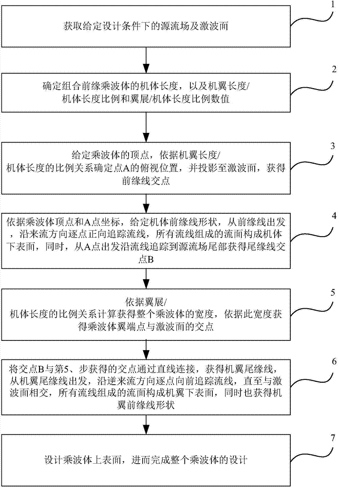
[0020] The technical solutions in the embodiments of the present invention will be clearly and completely described below in conjunction with the accompanying drawings in the embodiments of the present invention. Obviously, the described embodiments are only a part of the embodiments of the present invention, rather than all the embodiments. Based on the embodiments of the present invention, all other embodiments obtained by those of ordinary skill in the art without creative work shall fall within the protection scope of the present invention.

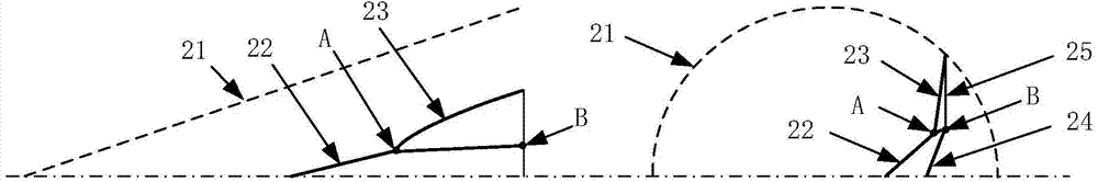
[0021] Such as figure 1 Shown is a schematic flow chart of a method for designing a combined leading edge waverider according to an embodiment of the present invention. figure 2 This is a schematic diagram of the design scene of the combined leading edge waverider according to the embodiment of the present invention, where 21 is the shock surface, 22 is the front edge of the body, 23 is the leading edge of the wing, 24 is the trailing edg...


PUM


Abstract

The embodiment of the invention provides a combined front-edge wave rider design method and a combined front-edge wave rider. According to the method, the appearance of the wave rider is divided into two parts, namely an engine body and a wing, and then the method of defining a front / rear edge curve is adopted, so that the design flexibility of the wave rider can be effectively improved, and the appearance more close to the actual can be acquired. The lower surface of the wing is intersected with a shock wave surface so as to form a wing front-edge line, and then the combined front-edge line of the wave rider is obtained; when the method is used for designing, not only can the features of the wave rider be guaranteed, but also the length-width ratio is flexible and the straightness of the tailing edge is guaranteed, the design method is more suitable for the actual aircraft. The lower surface of the engine body can be designed by using a positive filament line tracing method for giving the front-edge line, the lower surface of the wing can be designed by using an adverse filament line tracing method for riving the tailing-edge line. The main application range of the design method provided by the embodiment of the invention is configuration design for various hypersonic aerocrafts, and the design method is particularly suitable for designing future hypersonic aircrafts or gliding type aircrafts.

Description

Technical field [0001] The invention relates to a high lift / high lift-to-drag ratio configuration design of a hypersonic vehicle, in particular to a design method of a combined leading edge waverider and a combined leading edge waverider. Background technique [0002] The configuration design of new high-speed aircraft is a hot issue in aircraft development. Due to the high-speed flight conditions, the shock wave resistance and frictional resistance of the aircraft increase sharply, resulting in the so-called "lift-to-drag barrier". This problem has also given birth to many new conceptual configurations, one of which is the waverider configuration. This configuration is designed based on a given flow field through shock surface cutting and streamline tracking. Under the design flight conditions (given Mach number, angle of attack, etc.), the bow shock generated during high-speed flight is completely attached to There is no flow leakage on the outer edges of the aircraft and the...

Claims


Application Information

Patent Timeline
Patent Type & Authority Applications(China)
IPC IPC(8): B64C23/00
Inventor 崔凯李广利肖尧
Owner INST OF MECHANICS - CHINESE ACAD OF SCI
Why Eureka
Try Eureka