Hydraulic lifting device capable of automatically dropping and automatic pile dropping method thereof

A hydraulic lifting device and self-lowering technology, which is applied in the field of marine engineering, can solve the problems of slow pile-down speed, easily damaged bolts, energy consumption, etc., and achieve the effect of fast pile-down speed

Inactive Publication Date: 2015-06-24
KEEN OFFSHORE ENG CO LTD
View PDF6 Cites 9 Cited by
  • Summary
  • Abstract
  • Description
  • Claims
  • Application Information

AI Technical Summary

Problems solved by technology

However, the existing hydraulic ring beam lifting device adopts a step-by-step descending method for both pile loading and pile insertion, which not only slows down the pile, but also requires additional energy consumption
However, because the existing hydraulic ring beam lifting device generally fixes the ring beam and the pile legs through bolts, if the bolts are simply pulled out to make the pile legs fall naturally, the bolts will be easily damaged

Method used


Image

  • Hydraulic lifting device capable of automatically dropping and automatic pile dropping method thereof
  • Hydraulic lifting device capable of automatically dropping and automatic pile dropping method thereof

Examples


Embodiment Construction

[0012] The technical solutions claimed in the present invention will be further described in detail in conjunction with the accompanying drawings and specific embodiments.

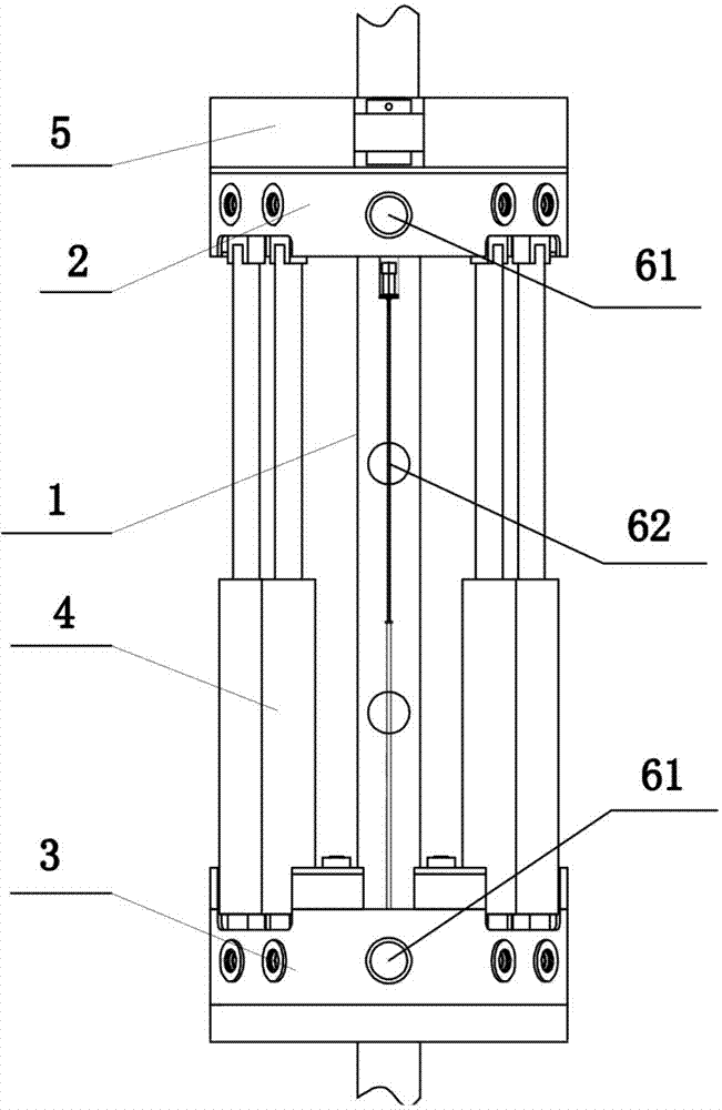
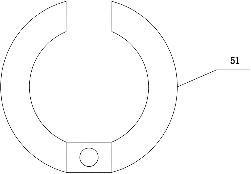
[0013] like figure 1 As shown, in this embodiment, the lifting device includes a positioning pile 1 , an upper ring beam 2 , a lower ring beam 3 , a lifting cylinder 4 and a clamper 5 . The positioning pile 1 runs through the upper ring beam 2 and the lower ring beam 3 in the longitudinal direction and makes a sliding connection between the positioning pile 1 and the upper ring beam 2 and the lower ring beam 3 . The lifting cylinder 4 is longitudinally connected between the upper ring beam 2 and the lower ring beam 3, and the driving of the lifting cylinder 4 makes the upper ring beam 2 and the lower ring beam 3 move relative to each other along the positioning pile 1 between the two ring beams, wherein The lower ring beam 3 is fixedly connected with the hull, and the upper ring beam 2 can move up and dow...


PUM


Abstract

The invention discloses a hydraulic lifting device capable of automatically dropping and an automatic pile dropping method thereof. The hydraulic lifting device capable of automatically dropping comprises a gauge pile, an upper ring beam, a lower ring beam and lifting oil cylinders; the upper ring beam or the lower ring beam is fixedly connected with a hull, the lifting oil cylinders are longitudinally connected with the upper ring beam and the lower ring beam, and the relative lifting and dropping between the upper ring beam and the lower ring beam are achieved through being driven by the lifting oil cylinders; the gauge pile vertically penetrates through the upper ring beam and the lower ring beam and is connected with the upper ring beam and the lower ring beam in a sliding mode, the gauge pile fixes the relative position with the upper ring beam and the lower ring beam through a pin mechanism, and the hydraulic lifting device capable of automatically dropping further comprises a clamp holder used for clamping and fixing the gauge pile.

Description

technical field [0001] The invention relates to the technical field of marine engineering, in particular to a self-lowering hydraulic lifting device and a self-lowering pile lowering method thereof. Background technique [0002] The existing hydraulic ring beam lifting device uses the cooperation of the upper and lower ring beams to move the legs up and down step by step, and is powered by an independent hydraulic drive system to ensure that the legs can overcome the impact caused by mud, sand and gravel. Resistance and the weight of the lifting platform itself, inserting (pulling) the legs into (pull off) the seabed and lifting the entire ship. The process from lowering the pile legs to inserting them into the seabed can be decomposed into two steps. First, lower the pile legs until they touch the bottom and contact the seabed. Processes become instrumented. Generally speaking, the resistance that the pile leg receives when laying down the pile is mainly the resistance of...

Claims


Application Information

Patent Timeline
Patent Type & Authority Applications(China)
IPC IPC(8): E02B17/08E02B17/06
CPCE02B17/0809E02B17/06
Inventor 李光远吴平平陆军张静波马振军
Owner KEEN OFFSHORE ENG CO LTD
Why Eureka
Try Eureka