Hazardous waste incineration fly ash self-cleaning device

A self-cleaning, fly ash technology, applied in the direction of incinerators, combustion methods, lighting and heating equipment, etc., can solve the problems of not considering the combustion of hazardous waste, not taking into account, and reducing the incineration space

Active Publication Date: 2021-06-15
湖州明境环保科技有限公司
View PDF12 Cites 0 Cited by
  • Summary
  • Abstract
  • Description
  • Claims
  • Application Information

AI Technical Summary

Problems solved by technology

[0004] However, this patent only discloses the separation of hazardous waste, but this patent does not take into account how the sent hazardous waste is concentrated at the central high-temperature place of the incineration equipment for combustion, and does not take into account that a large amount of hazardous waste is input into the incineration equipment Finally, the incineration space becomes smaller, how to quickly expand the space for rapid incineration of hazardous waste

Method used


Image

  • Hazardous waste incineration fly ash self-cleaning device
  • Hazardous waste incineration fly ash self-cleaning device
  • Hazardous waste incineration fly ash self-cleaning device

Examples


Embodiment

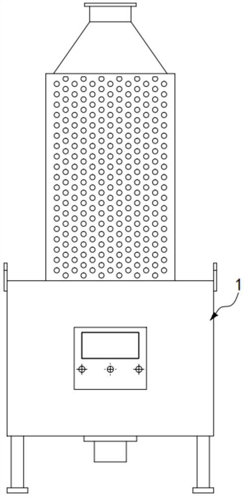
[0057] like Figure 1 to Figure 10 As shown, a hazardous waste incineration fly ash self-cleaning device includes pretreatment and feeding equipment, incineration equipment, waste heat boiler equipment, quenching device and deacidification and dust removal equipment. The incineration equipment includes a primary combustion chamber and a secondary combustion chamber. chamber, the primary combustion chamber includes:

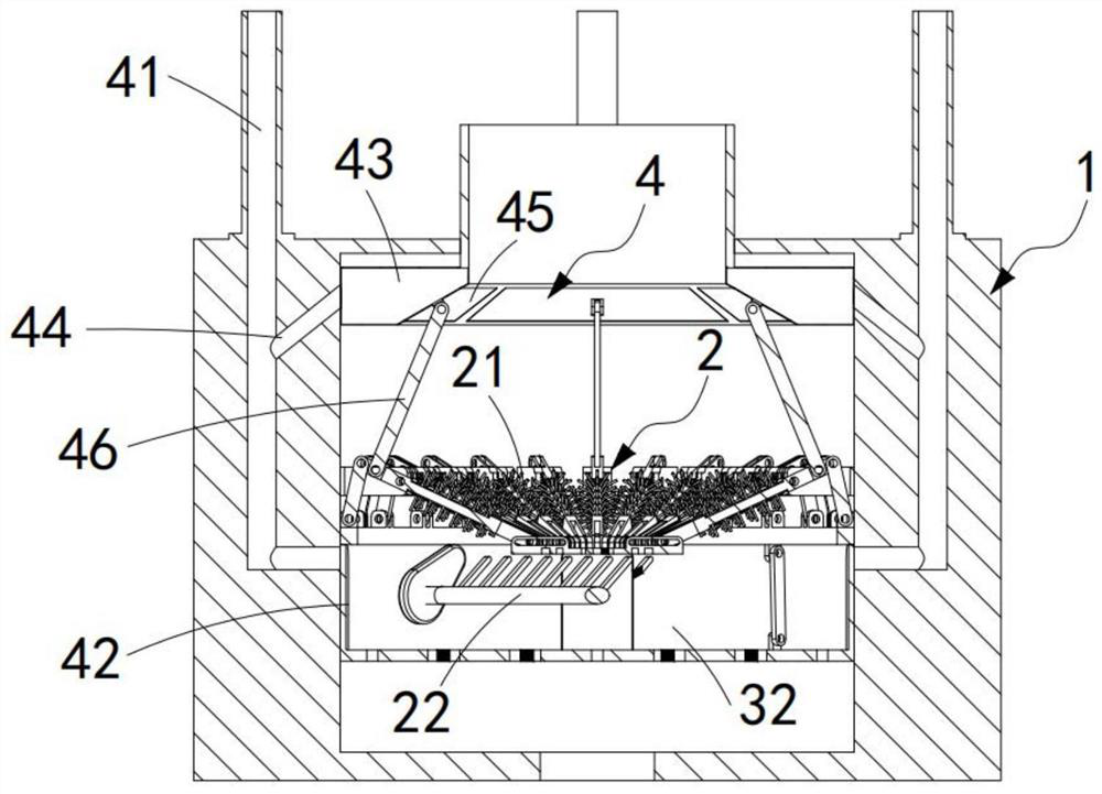
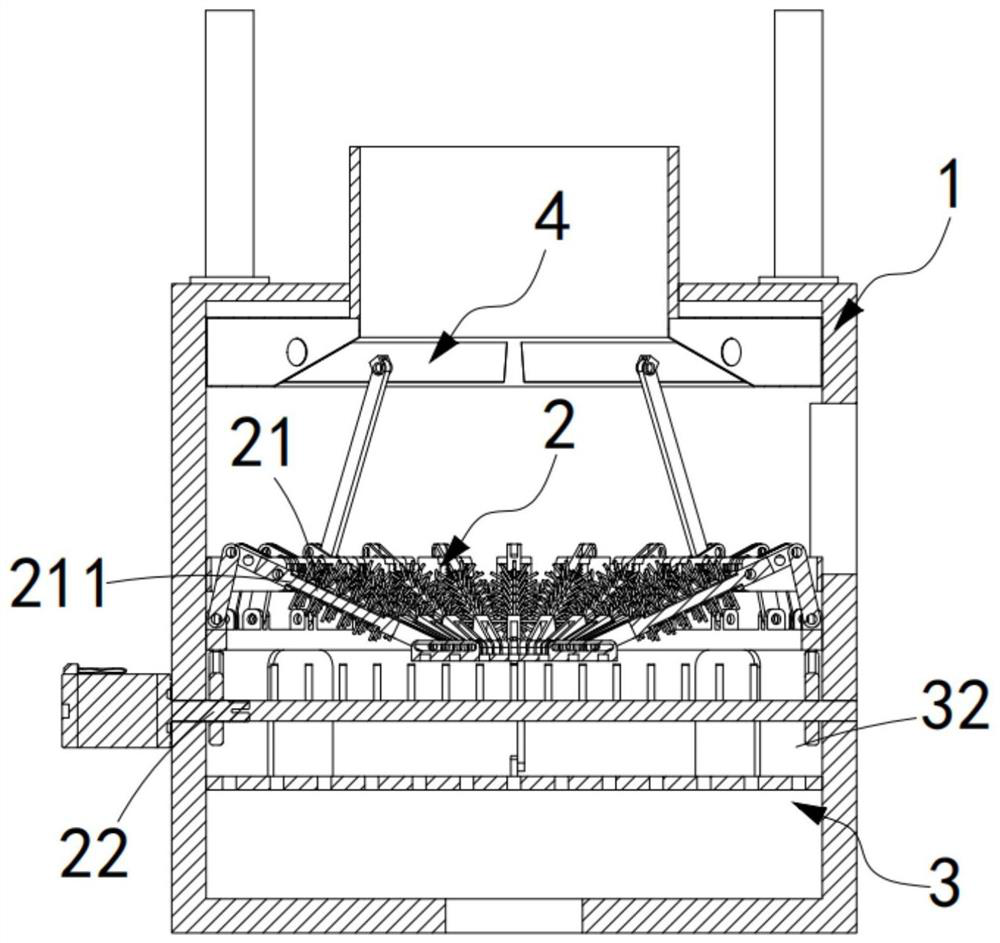
[0058] Combustion chamber body 1, the combustion chamber body 1 is provided with a combustion space, and the combustion chamber body 1 is connected with the feeding device;

[0059] A dismantling mechanism 2, the dismantling mechanism 2 is installed in the lower part of the combustion space in the combustion chamber body 1, the dismantling mechanism 2 is used to disperse the hazardous wastes input by the rotary kiln, and the dismantling mechanism 2 includes dismantling A material assembly 21 and a drive assembly 22. The material removal assembly 21 is installed o...

Embodiment approach

[0084] As a preferred embodiment, the fly ash self-cleaning mechanism 4 includes:

[0085] A combustion-supporting passage 41, the combustion-supporting passage 41 is arranged in the side wall of the combustion chamber body 1, a mixture of a combustion-supporting agent and air circulates in the combustion-supporting passage 41, and the outlet of the combustion-supporting passage 41 is located in the auxiliary combustion zone 32 ;as well as

[0086] Movable sealing plate 42, described movable sealing plate 42 is installed on the described fire grate 3, this movable sealing plate 42 switches the outlet of described combustion-supporting channel 41 with the lifting of described fire grate 3;

[0087] The ash collection bin 43, the ash collection bin 43 is arranged directly above the dismantling mechanism 2, the ash collection bin 43 communicates with the combustion-supporting channel 41 through a communication branch pipe 44, and the communication branch pipe 44 is arranged obliq...


PUM


Abstract

The invention relates to the technical field of hazardous waste incineration treatment and processing, in particular to a hazardous waste incineration fly ash self-cleaning device which comprises pretreatment and feeding equipment, incineration equipment, waste heat boiler equipment, a quick cooling device and deacidification and dust removal equipment; the incineration equipment comprises a first-stage combustion chamber and a second-stage combustion chamber; the first-stage combustion chamber comprises a combustion chamber body, a material disassembling mechanism, a grate and a fly ash self-cleaning mechanism; the material disassembling mechanism is matched with the fly ash self-cleaning mechanism; when the material disassembling mechanism splits the hazardous waste, an ash collecting bin in the fly ash self-cleaning mechanism is driven to be opened, fly ash generated in the splitting process is collected through the ash collecting bin, and the fly ash is guided to flow into an auxiliary combustion area; and the fly ash is re-deposited on the grate in cooperation with the arrangement of the auxiliary combustion area, so that the technical problem that the fly ash is raised in the splitting combustion process is solved.

Description

technical field [0001] The invention relates to the technical field of incineration treatment and processing of hazardous waste, in particular to a self-cleaning device for incineration fly ash of hazardous waste. Background technique [0002] Hazardous waste incineration technology based on combustion equipment has become one of the hazardous waste disposal technologies supported by my country's environmental policy because of its high-strength destructiveness to toxic pollutants and wide adaptability to materials. The current technology of incineration equipment Hazardous wastes are crushed before disposal. Although the incineration efficiency can be improved to a certain extent, due to the reduction in volume after crushing, the accumulation density of the waste is relatively high. If the feeding interval is not well controlled, it will lead to The interior of the garbage cannot be incinerated and penetrated, causing the reverse effect. [0003] In the patent application n...

Claims


Application Information

Patent Timeline
Patent Type & Authority Applications(China)
IPC IPC(8): F23G5/00F23G5/44F23G5/50
CPCF23G5/00F23G5/44F23G5/444F23G5/50Y02E20/30
Inventor 周志江蔡波董国君吴健陈锋郑小伦
Owner 湖州明境环保科技有限公司
Why Eureka
Try Eureka