Three-branch bi-directional hydraulic squeezing and expanding machine

A two-way hydraulic and extrusion machine technology, which is applied in construction, sheet pile walls, foundation structure engineering, etc., can solve the problems that affect the stability of buildings, the bearing plate space is easy to collapse, and the bearing capacity cannot be obtained, so as to improve the application Effect and efficiency, achieve consistency and stability, and improve the effect of axial running ability

Active Publication Date: 2015-06-24
北京聚力挤扩科技开发有限公司
View PDF9 Cites 0 Cited by
  • Summary
  • Abstract
  • Description
  • Claims
  • Application Information

AI Technical Summary

Problems solved by technology

[0006] 1. When forming the load-bearing plate, the bow pressing arm needs to swing at least six times in the radial direction. In theory, a mallet-shaped disc space can be formed; but in actual operation, although the machine head swings Angle, but because the bow pressing arm is fixed on the plunger rod of the oil cylinder, the plunger rod and the machine head are connected coaxially, and relative displacement inevitably occurs during the period, resulting in the swing angle of the bow pressing arm and the swing angle of the machine head There is a deviation, so the theoretical pile plate cannot be formed, which affects the stability of the pile foundation and cannot achieve the proper load-bearing function
[0007] 2. When the bow pressi

Method used


Image

  • Three-branch bi-directional hydraulic squeezing and expanding machine
  • Three-branch bi-directional hydraulic squeezing and expanding machine
  • Three-branch bi-directional hydraulic squeezing and expanding machine

Examples


Embodiment Construction

[0025] The present invention will be further described in detail below through the specific examples, the following examples are only descriptive, not restrictive, and cannot limit the protection scope of the present invention with this.

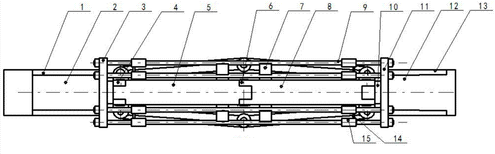
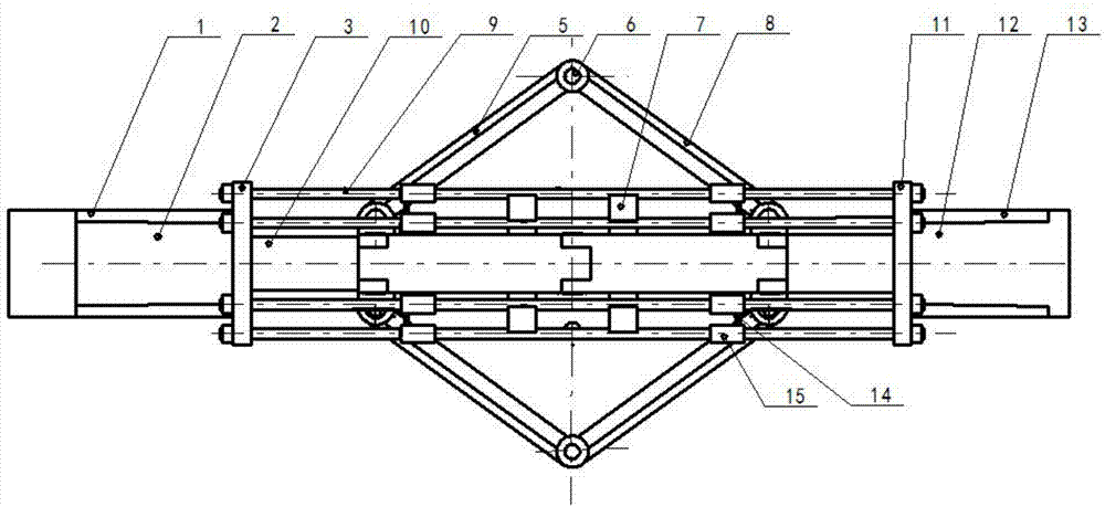
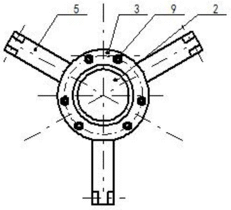
[0026] A three-fork two-way hydraulic extrusion machine, comprising an upper head 1, a lower head 13, an upper bow pressing arm 5, a lower bow pressing arm 8, an upper oil cylinder 2 and a lower Oil cylinder 12, the piston rod 10 ends of the upper and lower oil cylinders are all hinged through the hinge seat 4 and one end of the upper bow pressing arm and the lower bow pressing arm are hinged, and the other ends of the upper bow pressing arm and the lower bow pressing arm are hinged through the middle hinge seat 6. The upper bow pressing arm and the lower bow pressing arm are coaxially and evenly spaced and hinged on the ends of the respective piston rods. The upper bow pressing arm and the lower bow pressing arm shown in the drawings of this...


PUM


Abstract

The invention relates to a three-branch bi-directional hydraulic squeezing and expanding machine. The three-branch bi-directional hydraulic squeezing and expanding machine comprises an upper machine head, a lower machine head, upper-bow pressing arms and lower-bow pressing arms, and is characterized in that an upper oil cylinder and a lower oil cylinder are coaxially and fixedly installed inside the upper machine head and the lower machine head respectively, one end of a piston rod of the upper oil cylinder is hinged to one ends of the upper-bow pressing arms through a hinging seat, one end of a piston rod of the lower oil cylinder is hinged to one ends of the lower-bow pressing arms through a hinging seat, the other ends of the upper-bow pressing arms are hinged through a middle hinging seat, the other ends of the lower-bow pressing arms are hinged through a middle hinging seat, and the upper-bow pressing arms and the lower-bow pressing arms are coaxially and evenly distributed at ends of the piston rods respectively in a spaced mode and form a three-branch shape. The upper-bow pressing arms and the lower-bow pressing arms are all power-bow pressing arms, the upper machine head and the lower machine head are coaxially and fixedly provided with a support frame shaped like a mouse cage, the support frame is in rigidity connection with the machine heads and can limit the bow pressing arms, therefore, synchronism between the swing angle of the machine heads and the swing angle of the bow pressing arms can be effectively achieved, deviation between the swing angle of the bow pressing arms and the swing angle of the machine heads is avoided, and a formed disk is ideal.

Description

technical field [0001] The invention belongs to the field of building pile foundations, and relates to a load-bearing plate and a load-bearing fork forming device for extruded and expanded cast-in-place piles, in particular to a three-fork two-way hydraulic extruded and expanded machine. Background technique [0002] Cast-in-situ piles are roughly divided into straight-rod piles and load-bearing disc piles. Straight-rod piles are mainly used for hard foundations, while force-bearing disc piles are mainly used for soft foundations. At present, the load-bearing disc piles are usually made by special forming equipment. The applicant found the following two typical published patent documents by searching the published patent documents: [0003] 1. A forming device for piles with branches and / or bearing plates (CN2332754). When the device starts to operate, it is easy to make the bow pressure extrusion forming mechanism extrude outward. The above-mentioned equipment includes sy...

Claims


Application Information

Patent Timeline
IPC IPC(8): E02D5/44E02D5/48
Inventor 齐迎春
Owner 北京聚力挤扩科技开发有限公司
Why Eureka
Try Eureka