

A Friction Stir Welding Method for Longitudinal Seam of Carrier Rocket Tank
A friction stir welding and launch vehicle technology, which is applied in welding equipment, non-electric welding equipment, attack equipment, etc., can solve the problem that the distance between the stirring needle and the back plate cannot be measured in real time, and achieve the effect of stable and reliable joint quality
Active Publication Date: 2012-03-07
CAPITAL AEROSPACE MACHINERY
View PDF0 Cites 7 Cited by
- Summary
- Abstract
- Description
- Claims
- Application Information
AI Technical Summary
Problems solved by technology
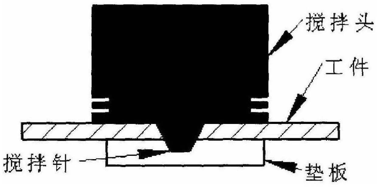
On the backing plate, due to the obstruction of the workpiece, the distance between the stirring needle and the backing plate cannot be measured in real time, and there is a root defect
Method used
View moreImage
Smart ImageViewing Examples

Examples
Embodiment Construction
[0026] In the present invention, the stirring head can adopt the structure shown in Table 1 when carrying out the friction stir welding of the longitudinal seam of the carrier rocket storage tank.
[0028]
[0030] Tank longitudinal seam friction stir welding adopts the welding sequence of formal welding after tack welding. Positioning welding adopts 5mm diameter stirrer
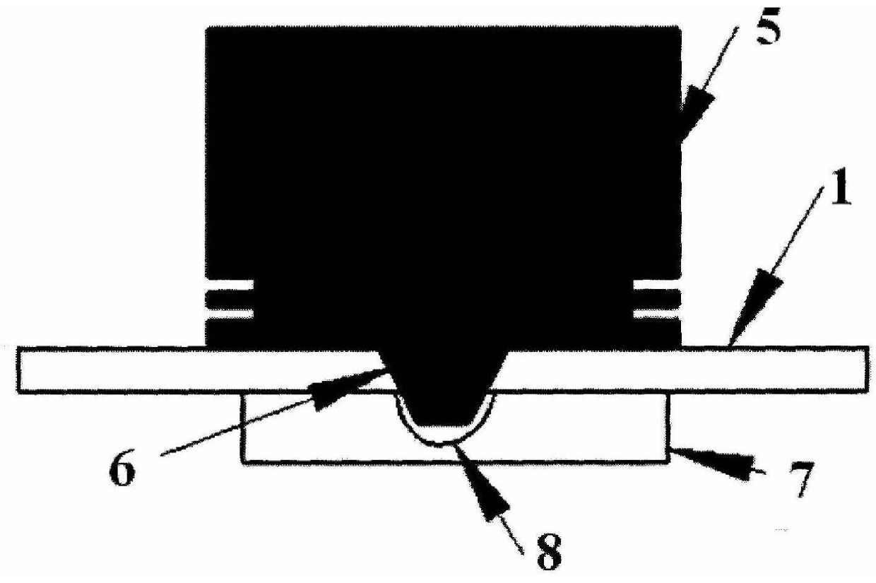
[0035] The diameter of the above-mentioned welding leakage groove 8 can be 6~10mm, and the depth can be 0.5~2mm.
[0038] The foregoing are only some embodiments of the present invention. It should be noted that for those of ordinary skill in the art
Login to View More PUM
 Abstract
A kind of friction stir welding method for the longitudinal seam of the carrier rocket storage tank according to the present invention, which adopts friction stir welding to weld the longitudinal seam of the carrier rocket storage tank, and fixes the two plates to be welded by a small clip tool, and makes the two plates to be welded The gap between the welding plates is less than 0.2mm; there is a welding leak groove with a depth of 0.6mm at the position of the stirring needle on the backing plate where the two plates are placed to be welded; when friction stir welding, the welding is firstly performed after tack welding and then formal welding Sequentially, take out the small clip tooling after the tack welding, and then plug the hole where the small clip tooling is placed with a plug of the same material, and then perform formal welding. The method of the invention ensures the assembly accuracy of the friction stir welding, realizes that the gap between the butt joint surfaces is less than 0.2mm, and realizes that the distance between the stirring needle and the backing plate has sufficient margin, thereby preventing the defects of incomplete penetration and the defects of the stirring needle piercing the backing plate generation.
Description
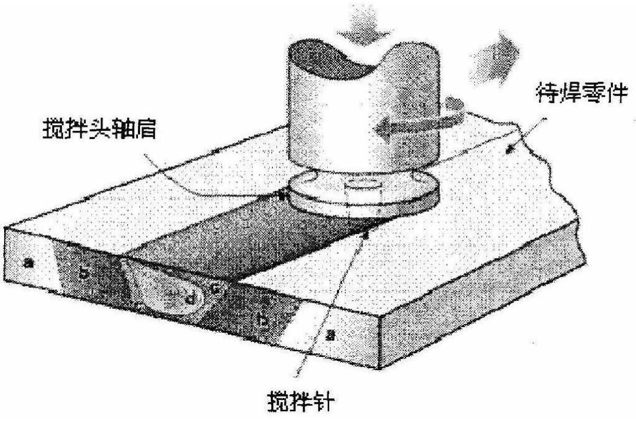
A friction stir welding method for longitudinal seams of carrier rocket tanks Technical field The present invention belongs to aerospace product processing method, be specifically related to a kind of thin-walled, large-scale, sealing structural member long straight weld seam Friction stir welding method. Background technique Friction stir welding technology is a kind of solid phase connection new technology invented by British Welding Institute in 1991, which is based on This principle is shown in Figure 1. The high-speed rotating stirring head plunges into the workpiece and moves along the welding direction. When the stirring head is in contact with the workpiece Frictional heat is generated at the part, so that the nearby metal forms a plastic softening layer, and the softening layer is filled and stirred under the action of the rotation of the stirring head The cavity formed behind the needle, and the solid phase welding method of material connection is realized u...
Claims
Login to View More Application Information
Patent Timeline
 IPC IPC(8): B23K20/12B23K20/26F42B15/00
Inventor刘宪力孙忠绍赵衍华罗军张丽娜朱平萍
OwnerCAPITAL AEROSPACE MACHINERY