Method for reliably connecting bridge printed circuit boards of optical transceivers and positioning component

A technology for printed circuit boards and optical transceivers, which is applied in the direction of assembling printed circuits with electrical components and printed circuits connected with non-printed electrical components, and can solve the problem of increasing the internal stress of flexible bridging printed circuit boards and modules Difficult to assemble high-grade products, difficult to control the heating time, etc., to achieve the effect of high one-time pass rate, good consistent shape, and low control difficulty

CN101652031BInactive Publication Date: 2011-09-07SUPERXON (CHENGDU) TECH LTD
0 Cites 0 Cited by

Patent Information

Authority / Receiving Office
CN · China
Patent Type
Patents(China)
Current Assignee / Owner
Publication Date
2011-09-07
Estimated Expiration
Not applicable · inactive patent

Smart Images

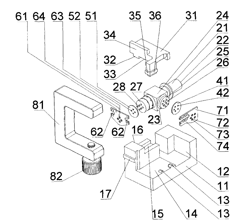
  • Figure 1
    Figure 1
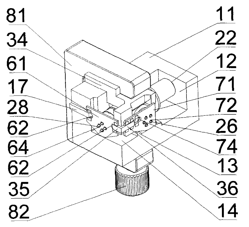
  • Figure 2
    Figure 2
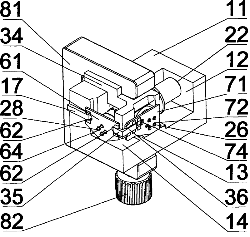
  • Figure 3
    Figure 3
Patent Text Reader

Abstract

The invention discloses a method for reliably connecting bridge printed circuit boards of optical transceivers and a positioning component, aiming to provide a method which has the advantages of convenient operation, reliable connection, high speed and high efficiency, does not damage the optical transceiver easily and can reliably connect pins of the receiving end and the transmitting end of an optical transceiver with a bridge printed circuit board. The method mainly comprises the following steps: preparing a U-shaped clamping groove on the side end of the bridge printed circuit board; arranging an insulating piece between the pins of the optical transceiver and the bridge printed circuit board; putting the optical transceiver into a positioning base seat which can limit the axial free degree of one end; sliding a fixed pressing block provided with a stop end surface and a guiding key into a guiding groove of the positioning base seat; clamping a crosslinking lug boss on the extension pin end of the fixed pressing block into the U-shaped clamping groove; moving the positioning component of the optical transceiver into an opening of a C-shaped clamping piece with a fastening bolton the open end; fixing the positioning component and finally fixing the pins of the transmitting end and the receiving end on a welding disk by tin soldering. The method has high efficiency and convenient operation.
Need to check novelty before this filing date? Find Prior Art

Description

technical field

[0001] The invention relates to a method and a positioning assembly for connecting the receiving end and sending end pins of the optical transceiver device and the bridging printed circuit board when assembling the optical transceiver device in the optical fiber communication system. Background technique

[0002] In the prior art, a bridging printed circuit board made of bendable and flexible material is provided with a through hole with a disc-shaped pad. When connecting the receiving end and the transmitting end of the optical transceiver device, the flexible bridging printed circuit board is close to the metal end faces of the receiving end and the transmitting end, and the pins on the vertical end faces of the receiving end and the transmitting end of the optical transceiver device pass through the through hole of the above-mentioned pad, tightly Paste bridges the surface of the printed circuit board. Solder by manual operation, and its pins are fixedly ...

Examples

Embodiment Construction

[0020] Below in conjunction with the best embodiment shown in the accompanying drawings, it will be further described in detail.

[0021] refer to figure 1 , the main body of the optical transceiver device 21 is a square structure, on which a receiving end and a sending end with end faces perpendicular to each other and with pins are arranged. The cylindrical body whose one side protrudes vertically from the front end face 22 is a light-conducting metal piece. The cylinder on the side opposite to the light-conducting metal part is the origin of the light-transmitting device 21 . The end face of the originating end is the originating metal end face 27 . The mutually insulated starting pins 28 protrude from the surface of the starting metal end surface 27 . There is a receiving end of the optical transceiver device 21 on one side of the main body in the middle part between the light-conducting metal piece and the sending end. The end face of the receiving end is the receivin...