Elastic swing roller mechanism for sliding door

A technology of roller mechanism and sliding door, which is applied in the direction of switches with braking devices, door/window accessories, building structures, etc. It can solve the problems of inability to interact, unable to meet user needs, and sliding doors that cannot be opened and closed directly. problems, to achieve the effect of convenient operation, simple and reasonable structure, and small opening and closing force

Active Publication Date: 2015-06-24
伍志勇
View PDF8 Cites 7 Cited by
  • Summary
  • Abstract
  • Description
  • Claims
  • Application Information

AI Technical Summary

Problems solved by technology

It is said that this structure can achieve a smooth and quiet closing effect by using damping under the condition of large impact force, and effectively protects the moving parts, reduces wear and prolongs the service life; however, since the pulley block is a positioning assembly If there is an error in the production and assembly process or it cannot interact with the chute after long-term use, the sliding door cannot be opened and closed directly, which cannot meet the needs of users.

Method used


Image

  • Elastic swing roller mechanism for sliding door
  • Elastic swing roller mechanism for sliding door
  • Elastic swing roller mechanism for sliding door

Examples


Embodiment Construction

[0020] The present invention will be further described below in conjunction with the accompanying drawings and embodiments.

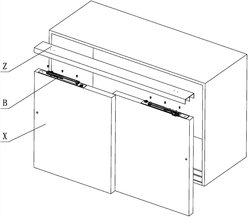
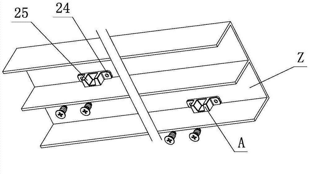
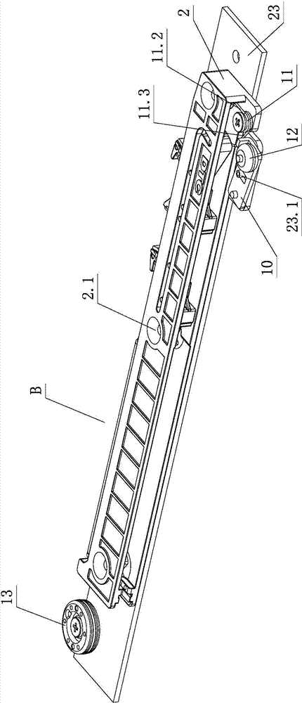
[0021] see Figure 1-Figure 5 , the elastic swing roller mechanism used for sliding doors, including fixed parts, movable parts and interacting toggle device A, reverse push and / or damping device B, the movable part is at least sliding door X, the fixed part At least the chute piece Z or the cabinet body; the toggle device A is set on the chute piece Z or the cabinet body, the reverse thrust and / or damping device B is set on the sliding door X, or the toggle device A is set on the On the sliding door X, the reverse thrust and / or damping device B is arranged on the chute member Z or the cabinet body; the reverse thrust and / or damping device B is provided with a fixed seat 23, and the fixed seat 23 is provided with a bracket 2 And the adapter 10 for positioning and swinging, wherein, the support 2 is provided with an elastic member 11, and the adapter 10...


PUM


Abstract

The invention discloses an elastic swing roller mechanism for a sliding door. The elastic swing roller mechanism comprises a fixed component, a movable component, a striking gear and a backstepping and / or damping device, wherein the striking gear and the backstepping and / or damping device act on each other. The movable component is at least the sliding door. The fixed component is at least a sliding groove part or a cabinet body. The striking gear is arranged on the sliding groove part or the cabinet body. The backstepping and / or damping device are / is arranged on the sliding door and provided with a fixed base. The fixed base is provided with a support and an adapter part achieving positioning swinging. The support is provided with an elastic part. A roller is arranged on the adapter part in a positioning rotating mode. The elastic part is provided with two or more bearing feet, wherein one bearing foot elastically acts on the support, the other bearing foot elastically acts on the adapter part, and therefore the adapter part and the roller can be elastically arranged on the fixed base in a positioning swing mode. The elastic swing roller mechanism has the advantages that the structure is simple, the performance is reliable, operation is convenient, all the components are connected compactly, positioning is accurate, the opening and closing process is stable and smooth, no noise is produced, the exerted force is small and the practicability is high.

Description

technical field [0001] The invention relates to an elastic swinging roller mechanism, in particular to an elastic swinging roller mechanism for a sliding door. Background technique [0002] The Chinese patent document number is CN201546563U, which disclosed a top suspension rail sliding door automatic closing system on August 11, 2010. It includes a suspension rail, a pulley block with damping, a pulley block, a bumper, and a damping connector. An I-shaped chute, the anti-collision device is placed at both ends of the suspension rail, the pulley block with damping and the pulley block are placed in the suspension rail, the damping connector is installed in the I-shaped chute, and the pulley block with damping is composed of a pulley block and a universal pulley Connector, damping, guide pulley connector and guide pulley, the damper is in the middle, one end is connected to the guide pulley connector, the guide pulley connector is connected to the guide pulley, the other end ...

Claims


Application Information

Patent Timeline
Patent Type & Authority Applications(China)
IPC IPC(8): E05D13/00
CPCE05D15/0691E05F1/16E05F5/003E05F5/027E05Y2201/412E05Y2201/614E05Y2600/12E05Y2600/456E05Y2600/626E05Y2800/205E05Y2800/24E05Y2900/20
Inventor 伍志勇
Owner 伍志勇
Why Eureka
Try Eureka