Load sensor monitoring method and system

A load sensor and load capacity technology, which is applied in construction and other fields, can solve the problems of inaccurate data collection of light rod indicator diagrams and difficulty in finding load sensors in time, so as to improve the production operation and management level, and the identification method is simple and feasible. Guarantee the effect of collection quality

Active Publication Date: 2015-06-24
PETROCHINA CO LTD
View PDF5 Cites 2 Cited by
  • Summary
  • Abstract
  • Description
  • Claims
  • Application Information

AI Technical Summary

Problems solved by technology

[0006] In order to solve the problem that it is difficult for the staff in the prior art to find the drift of the load sensor in time, and when the load sensor drifts too much to cause a large deviation in the output, the data acquisition of the polished rod indicator diagram is inaccurate. This paper The embodiment of the invention provides a load sensor monitoring method and system

Method used


Image

  • Load sensor monitoring method and system
  • Load sensor monitoring method and system
  • Load sensor monitoring method and system

Examples


Embodiment 1

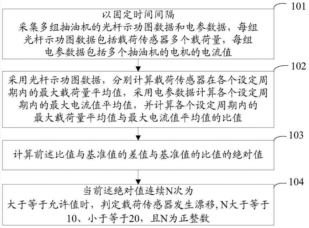
[0048] The embodiment of the present invention provides a load sensor monitoring method, the load sensor is suitable for measuring the load of the sucker rod of the pumping unit, see figure 1 , the method includes:

[0049]Step 101: Collect multiple sets of polished rod dynamometer data and electrical parameter data of the pumping unit at fixed time intervals, each set of polished rod dynamometer data includes multiple loads measured by the load sensor, and each set of electrical parameter data includes multiple The current value of the motor of the pumping unit.

[0050] Among them, the polished rod indicator diagram data also includes multiple displacement values ​​of the pumping unit that are measured synchronously with the load. The load is measured by the load sensor installed on the pumping unit, and the displacement value is measured by the displacement sensor installed on the pumping unit. Measured. The electrical parameter data can be measured by a current transform...

Embodiment 2

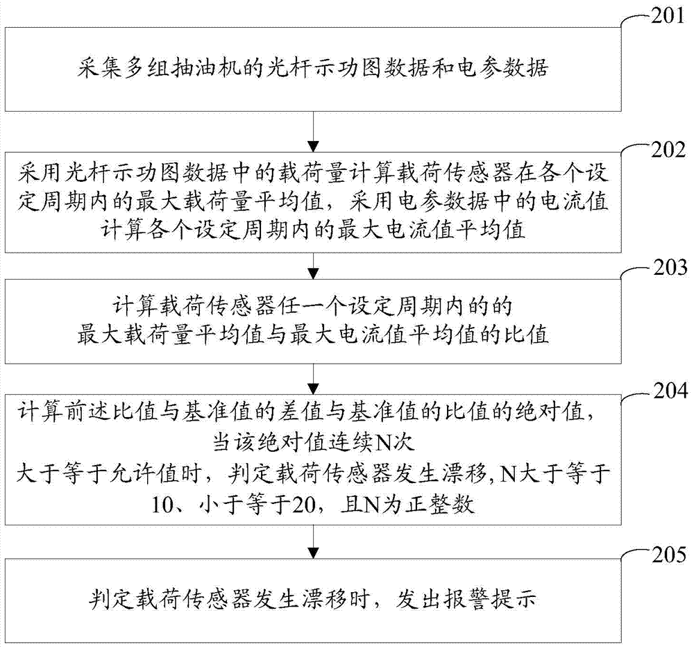
[0059] The embodiment of the present invention provides a load sensor monitoring method, the load sensor is suitable for measuring the load of the sucker rod of the pumping unit, see figure 2 , the method includes:

[0060] Step 201: Collect polished rod dynamometer data and electrical parameter data of multiple groups of pumping units.

[0061] Wherein, each set of polished rod dynamometer data includes multiple loads measured by the load sensor, and each set of electric parameter data includes current values ​​of motors of multiple pumping units. The polished rod indicator diagram data also includes multiple displacement values ​​of the pumping unit that are measured synchronously with the load. The load is measured by the load sensor installed on the pumping unit, and the displacement value is measured by the displacement sensor installed on the pumping unit. .

[0062] Preferably, the electrical parameter data is collected by a current transformer. The displacement sen...

Embodiment 3

[0095] An embodiment of the present invention provides a load sensor monitoring system, the load sensor is suitable for measuring the load of the sucker rod of the pumping unit, see image 3 , the system includes: a wellhead collector 31 and a host computer 32.

[0096] Wherein, the wellhead collector 31 is used for collecting polished rod dynamometer data and electrical parameter data of multiple groups of pumping units at fixed time intervals. Each set of polished rod dynamometer data includes multiple loads measured by the load sensor, and multiple displacement values ​​of the pumping unit measured synchronously with the loads, and the displacement values ​​are measured by the displacement sensor installed on the pumping unit. Each set of electrical parameter data includes current values ​​of motors of multiple pumping units. The current data can be measured by a current transformer.

[0097] The upper computer 32 is used to calculate the average value of the maximum load...


PUM


Abstract

The invention discloses a load sensor monitoring method and system and belongs to the field of oilfield digitalization. The method includes: acquiring multiple groups of polished rod indicator diagram data and electrical parameter data at fixed intervals, with each group of polished rod indicator diagram data including multiple load quantities and each group of electrical parameter data including multiple current values; through the polished rod indicator diagram data, calculating a maximum load quantity average of a load sensor in each set period, and through the electrical parameter data, calculating a maximum current value average in each set period and a ratio of the maximum load quantity average to the maximum current value average in each set period; calculating, in each set period, an absolute value of a ratio of a difference between the ratio and a reference value to the reference value; if the absolute value is greater than or equal to an allowed value N times continually, determining that the load sensors drift. N is a positive integer, belonging to [10, 20]. The load sensor monitoring method and system has the advantages that by determining whether the load sensor drifts, workers are enabled to maintain or change the drifted load sensors in time and quality of acquiring the polished rod indicator diagram data is guaranteed.

Description

technical field [0001] The invention relates to the field of digitalization of oil fields, in particular to a load sensor monitoring method and system. Background technique [0002] The polished rod indicator diagram is a graph that reflects the change law of the load of the suspension point of the pumping unit with its displacement value. In the daily production of oilfields, technicians monitor the bottomhole flow pressure in real time by testing the polished rod indicator diagram, combined with data such as the dynamic fluid level and casing pressure of the oil well, and then grasp the production and operation of the oil well in real time. Therefore, whether the collection quality of the polished rod dynamometer chart meets the requirements will inevitably affect the analysis of the production and operation of the oil well. If the polished rod dynamometer chart does not meet the requirements, it will lead to wrong analysis, which will bring unnecessary losses to the oil w...

Claims


Application Information

Patent Timeline
Patent Type & Authority Applications(China)
IPC IPC(8): E21B47/009
CPCE21B47/009
Inventor 李明江杨仓海穆谦益李珍邱亮于世春操红梅赵晓龙程世东辛宏邱奇张彬
Owner PETROCHINA CO LTD
Why Eureka
Try Eureka