transmission

A technology of transmission and clutch disc, applied in the direction of vehicle transmission, clutch, friction clutch, etc., can solve problems such as poor application

Active Publication Date: 2018-11-02
GM GLOBAL TECH OPERATIONS LLC
View PDF10 Cites 0 Cited by
  • Summary
  • Abstract
  • Description
  • Claims
  • Application Information

AI Technical Summary

Problems solved by technology

Furthermore, such a clutch is only poorly suited for automated operation with the aid of a servomotor, since the rotary motion of the servomotor must first be converted into a linear movement, or a gear train must be provided between the servomotor and the clutch lever in order to generate the the force required to move the clutch lever

Method used


Image

  • transmission
  • transmission
  • transmission

Examples


Embodiment Construction

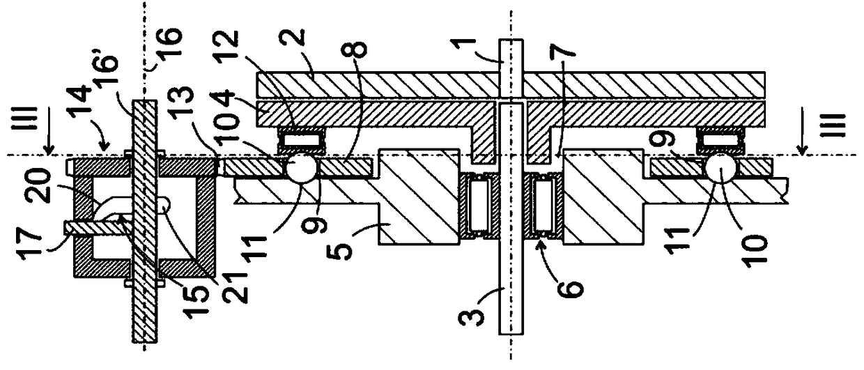
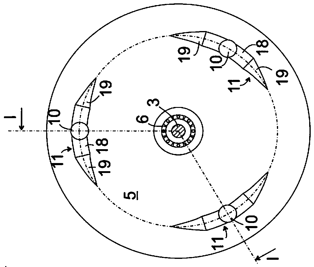
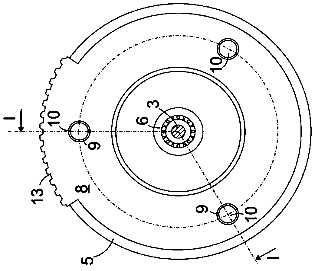
[0030] figure 1 The clutch pack according to the first embodiment of the invention is shown in a simplified diagram. A first clutch disk 2 is mounted on the first shaft 1 in a rotationally fixed and axially immovable manner. A second shaft 3 is arranged coaxially opposite the end of the shaft 1 . The second shaft 3 supports the second clutch disk 4 in a rotationally fixed but axially displaceable manner. The shaft 3 extends through the bore of a plate-shaped bracket 5 which is fixedly connected to the housing of the clutch (not shown) or forms a wall of the housing. The shaft 3 is held and guided in the opening 7 of the carrier 5 by means of a rolling bearing 6 .

[0031] Extending coaxially to the shaft 1 , a disk-shaped holder 8 with a plurality of axial bores 9 extends annularly around the opening 7 and holds an adjusting body 10 in each case. The adjusting body 10 is here in the shape of a ball; other shapes, such as cylindrical or frusto-conical, are likewise conceiva...


PUM


Abstract

A clutch assembly for a manual shift transmission includes a first shaft, which carries a first clutch disc, a second shaft that is coaxial to the first shaft. The second shaft carries an axially shiftable second clutch disc, a first ramp, of which at least one section describes a helical line that is coaxial to the shafts, and a first actuating body. The first actuating body is clamped between the first ramp and the second clutch disc and can be moved about a common axis of the shafts between an open position, in which the clutch discs are spaced from one another, and a closing position, in which the clutch discs contact one another in a frictionally joined manner.

Description

technical field [0001] The invention relates to a transmission having a clutch pack and a shift sleeve. Background technique [0002] The clutch of a conventional manual transmission is primarily designed to be operated by a clutch pedal and consists of two cooperating clutch discs and an annular clutch lever which is axially movable by pedal operation and which extends around the shaft of the clutch. The shift lever adjusts one of the clutch discs axially via the release disc acting as a lever. The lever element provided for actuating the clutch lever requires a large installation space not only in the axial direction but also in the radial direction. Furthermore, such a clutch is only poorly suited for automated operation with the aid of a servomotor, since the rotary motion of the servomotor must first be converted into a linear movement, or a gear train must be provided between the servomotor and the clutch lever in order to generate the the force required to move the ...

Claims


Application Information

Patent Timeline
Patent Type & Authority Patents(China)
IPC IPC(8): F16D23/12
CPCF16D21/06F16D13/40F16D13/42F16D13/52F16D2021/0646F16D2021/0676F16D2021/0684F16D2023/123F16H3/006F16H2003/0931F16H2200/0052
Inventor M.雷姆勒C.鲁布萨姆
Owner GM GLOBAL TECH OPERATIONS LLC
Why Eureka
Try Eureka