A reflective led lighting lamp

A technology of LED lighting and reflective surfaces, which is applied to lighting devices, lighting and heating equipment, and parts of lighting devices, etc. It can solve problems such as visual fatigue, uneven light irradiation, and affecting the lighting effect of LED lamps, and achieve extended use The effect of long life and simple structure of lamps and lanterns

Active Publication Date: 2017-09-05
四川源之康照明科技有限公司
View PDF8 Cites 0 Cited by
  • Summary
  • Abstract
  • Description
  • Claims
  • Application Information

AI Technical Summary

Problems solved by technology

[0004] In the existing high-power LED lamps, the LED light source is generally installed directly facing the ground, and the lumen efficiency of the LED is getting higher and higher, and the emitted light per unit area is getting stronger and stronger, and the direct light is not uniform, and it is irritating to the human eye. Larger, seriously affecting the lighting effect of LED lamps, long-term viewing, easy to cause visual fatigue and even vision loss

Method used


Image

  • A reflective led lighting lamp
  • A reflective led lighting lamp
  • A reflective led lighting lamp

Examples


Embodiment Construction

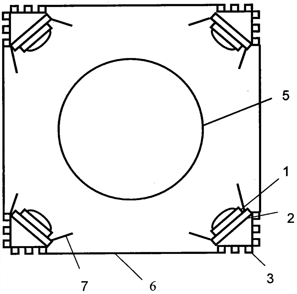
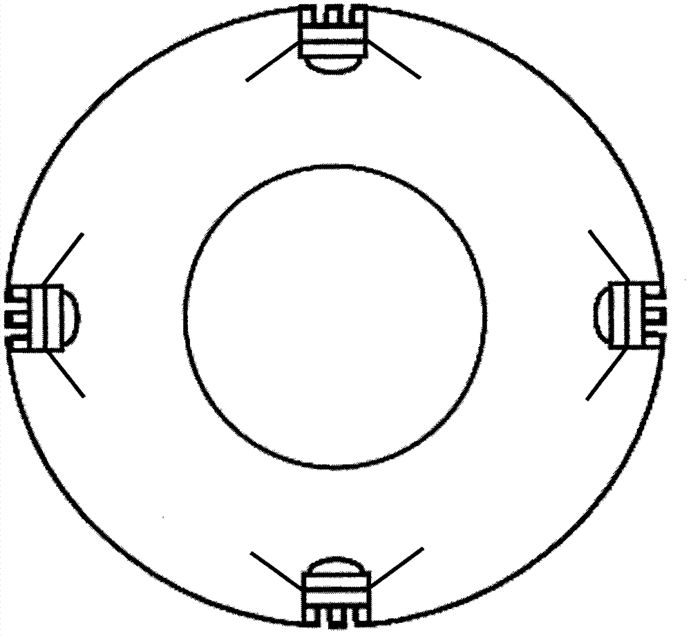
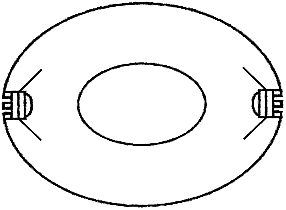
[0029] See Figure 1 to Figure 5 As shown, the present invention is a preferred example of a reflective surface LED outdoor lighting lamp, but the embodiment of the present invention is not limited thereto.

[0030] According to an embodiment of the present invention, FIG. 1 is a schematic diagram of several horizontal cross-sectional views of a reflective surface LED lighting lamp in the embodiment. In this design, the LED lighting lamp includes an illuminant LED lighting module 1 , a circuit board 2 , a heat sink 3 , a circuit power supply 4 , a reflector 5 , a light-transmitting cover 6 , a baffle plate 7 , and a rear cover 8 . The LED light-emitting module 1 is facing the convex part of the reflector, the LED light-emitting surface is facing the convex surface, and there is a gap between the LED light-emitting module and the reflector; the LED light-emitting module 1 is welded on the circuit board 2, and the circuit board is pasted on the heat-dissipating surface with heat...


PUM


Abstract

The invention provides a light reflection face LED illumination lamp. The light reflection face LED illumination lamp comprises a circuit board, LEDs and a light reflection cover used for reflecting light of the LEDs. The light reflection face of the light reflection cover is a protruding face. The light-emitting faces of the LEDs are right opposite to the protruding face. LED light-emitting module arrays are vertically placed or placed with an included angle between the LED light-emitting module arrays and the vertical direction. The central axis of the light reflection protruding face is in the vertical direction. The LEDs are arranged on the circuit board. A gap is reserved between the circuit board and the protruding face. The LEDs are located between the protruding face and the circuit board. The side, facing the protruding face, of the circuit board is coated with a light reflection layer. The circuit board is connected with a circuit power supply through a wire. The circuit board and the circuit power supply are arranged in a separated mode. Light of the LEDs is diffused through the protruding face, the light focused together is dispersed, the irradiation range is widened, and light can be uniform within the space range. The LEDs are located between the protruding face and the circuit board. The circuit board is pasted on a heat dissipation device through heat conduction glue and fixed through screws, the heat dissipation device is exposed in the air, and good thermal radiation and cross-ventilation are formed. The light reflection face LED illumination lamp has the advantages of being simple in structure, good in heat dissipation effect, more uniform in illumination, and the like.

Description

technical field [0001] The invention relates to the technical field of LED lighting, in particular to a reflective surface LED lighting lamp. [0002] technical background [0003] With the development of light-emitting diode technology, high-power LED technology has become increasingly mature. It has many advantages such as high luminous flux, long life, high reliability, and energy saving. It is the most potential light source to replace the existing lighting source. Existing LED lamps generally use multiple power LEDs in one lamp, so the heat dissipation of LEDs becomes an important factor affecting the use status and lifespan of LED lamps. However, the existing LED lamps generally adopt a closed structure, and the heat of the light source and the driving power cannot be dissipated in a timely and effective manner. Although some lamps also design a special heat dissipation structure, the structure is usually complicated and the heat dissipation effect is not good. The lig...

Claims


Application Information

Patent Timeline
Patent Type & Authority Patents(China)
IPC IPC(8): F21K9/60F21V7/04F21V19/00F21V7/22F21V23/06F21Y115/00F21K9/233F21K9/68F21Y115/10
CPCF21S2/00F21V7/041F21V7/043F21V7/22F21V19/001F21V23/06F21Y2101/00
Inventor 魏子涵
Owner 四川源之康照明科技有限公司
Why Eureka
Try Eureka