An expanded beam photoelectric composite connector

A photoelectric composite and connector technology, which is applied in the direction of connection, coupling of optical waveguides, components of connection devices, etc., can solve the problems of optical end face wear and service life, optical pin end face is easy to be polluted, etc.

Active Publication Date: 2017-09-05
CHINA ELECTRONICS TECH GRP NO 23 RES INST
View PDF7 Cites 0 Cited by
  • Summary
  • Abstract
  • Description
  • Claims
  • Application Information

AI Technical Summary

Problems solved by technology

[0007] The technical problem to be solved by the present invention is to provide a beam-expanding photoelectric composite connector, which can not only solve the problem that the end face of the optical pin of the existing photoelectric composite connector is easily polluted, and the wear of the optical end face affects the service life, but also can effectively avoid Influence of Electrical Contacts on Beam Expansion Optical Path

Method used


Image

  • An expanded beam photoelectric composite connector
  • An expanded beam photoelectric composite connector
  • An expanded beam photoelectric composite connector

Examples


Embodiment Construction

[0027] The present invention will be further described below in conjunction with the accompanying drawings and embodiments.

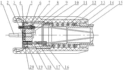
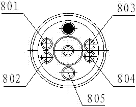
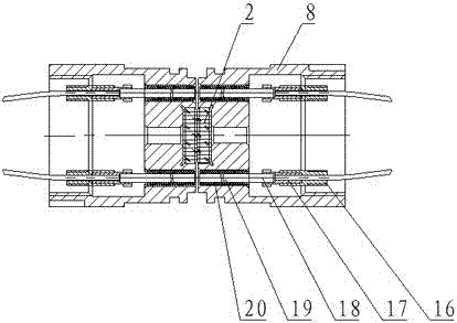
[0028] figure 1 It is a structural schematic diagram of the beam expanding photoelectric composite connector of the present invention; figure 2 It is a schematic diagram of the structure of the guide column hole and the installation hole of the beam expander photoelectric composite connector of the present invention.

[0029] See figure 1 and figure 2 , the beam expander photoelectric composite connector provided by the present invention includes a base body 8, wherein one end surface of the base body 8 is a smooth plane 2 and a guide column 1 is provided, and the guide column 1 is perpendicular to the smooth plane 2, and the The base 8 is provided with a guide post hole 805, and a mounting hole for fixing the electrical contact and the optical collimator assembly, the electrical contact is arranged in the mounting hole through an elastic member, a...


PUM


Abstract

The invention discloses a beam-expanded type photoelectric composite connector. The connector comprises a base body. One end face of the base body is a smooth plane and provided with a guide column. The guide column is perpendicular to the smooth plane. The base body is provided with guide column holes and mounting holes for fixing an electrical contact piece and an optical collimator assembly. The electrical contact piece is arranged in the mounting holes through elastic components. A shell is arranged outside the base body. The base body is fixedly connected with the shell through a middle sleeve and a locking sleeve. According to the beam-expanded type photoelectric composite connector, the guide column, the guide column holes and the mounting holes are arranged on the end face of the base body, meanwhile, a connector optical path is aligned with a circuit, and an optical path collimator is attached through the smooth plane of the connector base body end face so that the problems that the end faces of optical contact pins of an existing photoelectric composite connector are prone to being polluted, and the service life is affected due to wear to the optical end face can be solved; electric contact pins and electric jacks are arranged in the mounting holes in a floating mode through the elastic components, and the alignment state of the optical path is not affected when the electric contact pins and the electric jacks are inserted.

Description

technical field [0001] The invention relates to an optical connection device, in particular to a beam expanding type photoelectric composite connector. Background technique [0002] At present, the photoelectric composite connector mainly adopts the following structure: the optical path alignment part adopts the commonly used pin floating structure, that is, the optical fiber ferrule directly contacts the precision centering through the coupling sleeve, and there is a certain gap between the optical fiber ferrule and the peripheral parts , The tail of the pin is designed with a spring to form a floating structure, which can eliminate the error of peripheral parts or the axial, radial, and angular errors caused by the contact of the electrical pin to the optical path to a certain extent; the circuit part is the electrical pin commonly used in electrical connectors Structure with electrical jacks. [0003] The existing photoelectric composite connector structure mainly has th...

Claims


Application Information

Patent Timeline
Patent Type & Authority Patents(China)
IPC IPC(8): G02B6/38G02B6/32H01R13/631
CPCG02B6/32G02B6/3847G02B6/3874H01R13/631
Inventor 李晓黎胡宝根吴小钢吕姣姣
Owner CHINA ELECTRONICS TECH GRP NO 23 RES INST
Why Eureka
Try Eureka