Optical object tracking method and optical object tracking system

A tracking system, optical technology, applied in the direction of mechanical mode conversion, user/computer interaction input/output, computer components, etc., can solve the problem of small number of effective reference points, poor performance of object tracking and remote control, and resolution To achieve the effect of improving the performance of object tracking

Active Publication Date: 2015-06-24
PIXART IMAGING INC
View PDF4 Cites 4 Cited by
  • Summary
  • Abstract
  • Description
  • Claims
  • Application Information

AI Technical Summary

Problems solved by technology

In general, the traditional multi-point object tracking method has poor resolution for regularly changing background noise, and the number of effective reference points is small, which has the disadvantages of poor object tracking and remote control performance.

Method used


Image

  • Optical object tracking method and optical object tracking system
  • Optical object tracking method and optical object tracking system
  • Optical object tracking method and optical object tracking system

Examples


Embodiment Construction

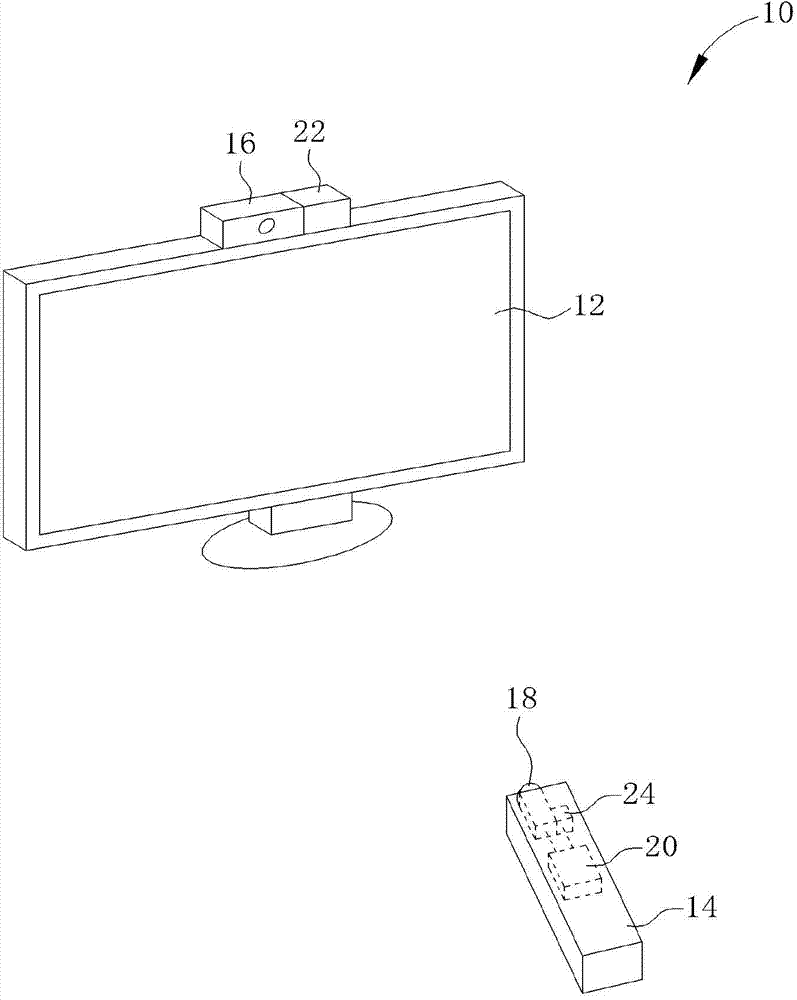
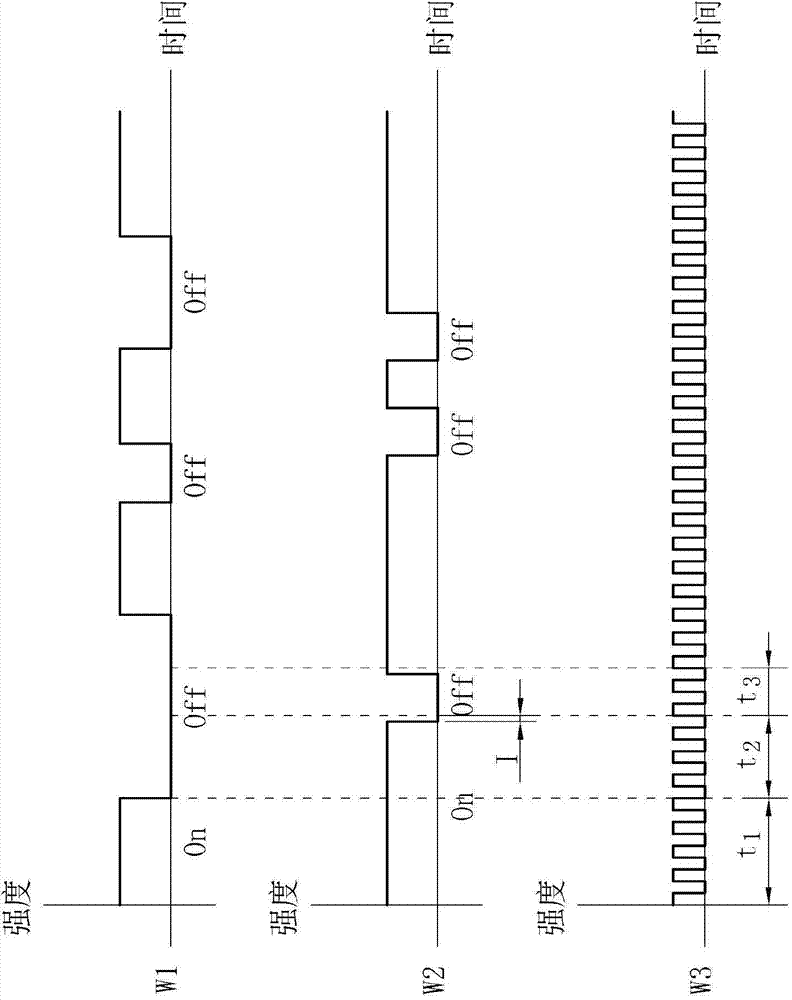
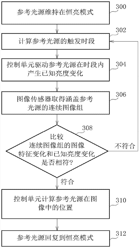
[0031] see figure 1 , figure 1 It is a schematic diagram of an optical tracking system 10 according to an embodiment of the present invention. The optical tracking system 10 includes a display 12 and a remote controller 14 . The remote control 14 is used to obtain the distance and angle of the remote control 14 relative to the display 12 , and generate corresponding coordinates for remote control. The display 12 includes a reference light source 16 , usually disposed on the upper end or the lower end of the display 12 . The remote controller 14 includes an image sensor 18 and a control unit 20 , and the control unit 20 is electrically connected to the image sensor 18 . The reference light source 16 will output a light signal with identifiable characteristics, such as a light signal with a specific blinking rate or a specific period of time, resulting in a known brightness change. The image sensor 18 takes successive sets of images covering the reference light source 16 . ...


PUM


Abstract

The invention discloses an optical object tracking method and an optical object tracking system. The optical object tracking method includes: acquiring a continuous image group containing a reference light source in a time period, and recognizing image feature changes of the continuous image group, wherein the reference light source is maintained in a constant-brightness mode and generates known brightness changes within the time period. The optical object tracking method further includes: comparing the image feature changes with the known brightness changes to determine whether starting of a preset function is needed or not, wherein the preset function refers to calculation of position information of the reference light source in image of the continuous image group. By means of the reference light source flickering randomly, object tracking efficacy of the optical object tracking system is effectively improved, and software and hardware of the optical object tracking system are simplified to reduce product cost.

Description

technical field [0001] The present invention relates to an optical object tracking method and its related optical tracking system, in particular to an optical object tracking method with high environmental noise resistance and its related optical tracking system. Background technique [0002] The traditional multi-point object tracking method regularly switches the reference point to generate a flickering light source. The image sensor simultaneously obtains continuous images covering the reference point. The controller finds the position of the reference point by analyzing the regular light and dark changes in the continuous image to generate the object. Coordinates needed to track the remote. The acquisition frequency of the image sensor and the synchronization error tolerance of the flickering light source of the reference point are small, so the reference point controller of the traditional multi-point object tracking method requires high precision, and the complexity of...

Claims


Application Information

Patent Timeline
Patent Type & Authority Applications(China)
IPC IPC(8): G06F3/01
Inventor 梁家钧
Owner PIXART IMAGING INC
Why Eureka
Try Eureka