
Inertial motion capture system capable of collecting and capturing face expression of object at the same time and operation method thereof

A motion capture and simultaneous acquisition technology is applied in the field of inertial motion capture systems to reduce system complexity, increase data transmission rate, and reduce data delay.

Active Publication Date: 2015-06-24
SHANDONG UNIV
View PDF8 Cites 8 Cited by
  • Summary
  • Abstract
  • Description
  • Claims
  • Application Information

AI Technical Summary

Problems solved by technology

[0007] The present invention combines the inertial motion capture system and the depth camera, overcomes the problem that the character's facial expression needs to be added later in the traditional film and television action capture, and simultaneously captures the action and expression, and preserves the original action expression of the performer to the greatest extent

Method used


Image

  • Inertial motion capture system capable of collecting and capturing face expression of object at the same time and operation method thereof
  • Inertial motion capture system capable of collecting and capturing face expression of object at the same time and operation method thereof

Examples


Embodiment 1

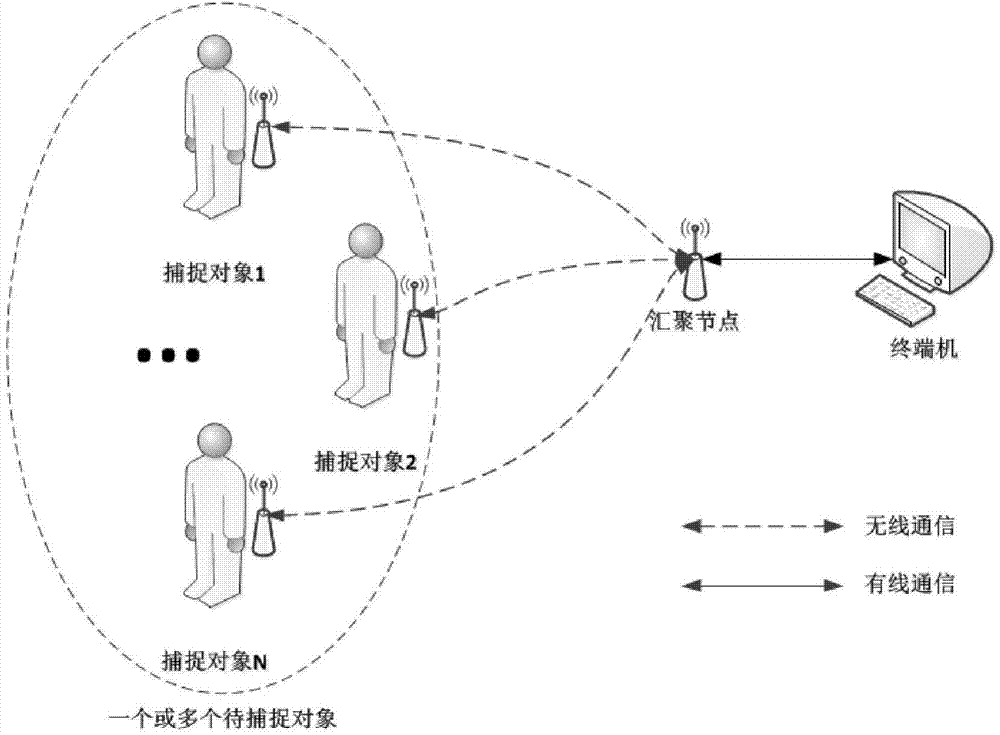
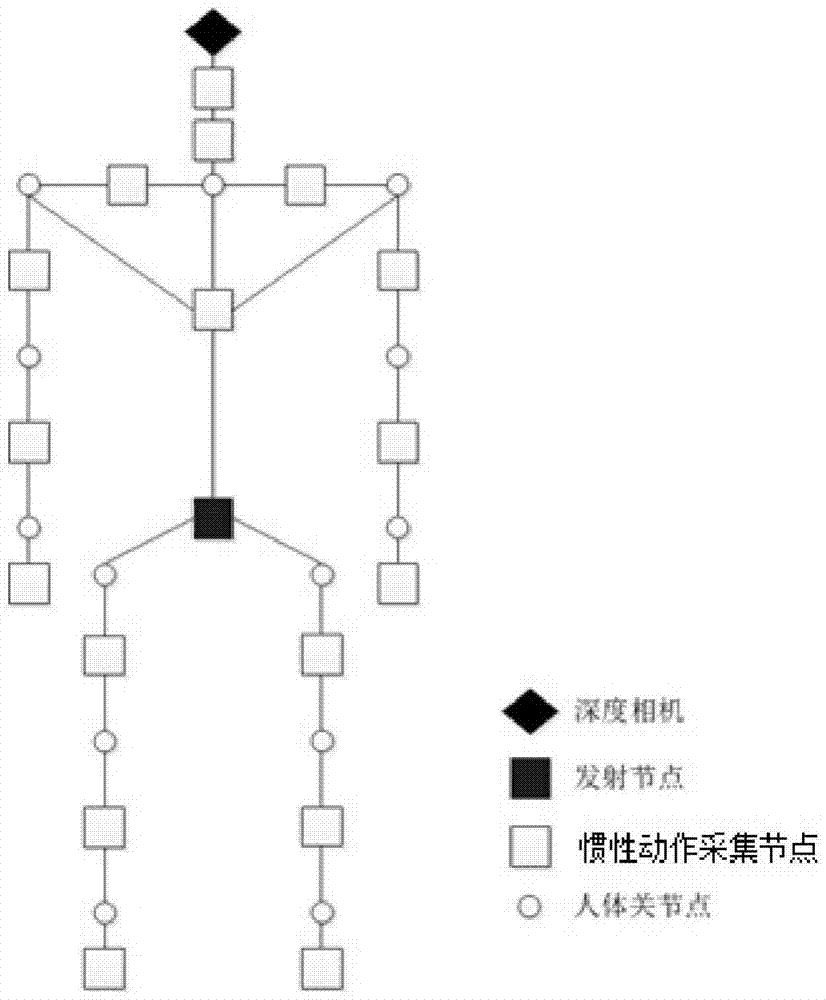
[0042]An inertial motion capture system capable of simultaneously collecting and capturing facial expressions of an object, comprising at least one depth camera, several inertial motion acquisition nodes, a transmitting node, a converging node and a terminal, the depth camera is connected to the transmitting node, the The transmitting node is connected to several inertial action collection nodes, the transmitting node is connected to the sink node, and the sink node is connected to the terminal;

[0043] The depth camera is used to collect information on the facial area of ​​the captured object, and establish a three-dimensional model for the facial area of ​​the captured object;

[0044] The inertial action collection node is used to collect the local position acceleration, angular velocity and magnetic strength of the capture object itself;

[0045] The transmitting node is used to collect the information collected by the depth camera and the information collected by the ine...

Embodiment 2

[0052] According to the inertial motion capture system described in Embodiment 1, the difference is that the depth camera is connected to the transmitting node in a wired manner.

[0053] The advantage of the design here is that the depth camera is connected to the transmitting node in a wired manner, which provides a higher data transmission rate than the wireless solution, and due to the reduction of wireless transmitting nodes, the collision of data in the wireless channel is reduced, improving The overall data transmission rate is improved, so that the sink node can obtain higher frequency human body posture data updates.

Embodiment 3

[0055] According to the inertial motion capture system described in Embodiment 1 or 2, the difference is that the transmitting node is connected to several inertial motion acquisition nodes via USB.


PUM


Abstract

An inertial motion capture system capable of collecting and capturing the face expression of an object at the same time comprises at least one depth camera, multiple inertial motion collection nodes, a transmitting node, an aggregation node and a terminal. The depth cameras are connected with the transmitting node, the transmitting node is connected with the inertial motion collection nodes and the aggregation node, and the aggregation node is connected with the terminal. Compared with the prior art, the inertial motion capture system can effectively capture the limb motion and face expression of the human body at the same time. Meanwhile, because the single-person inertial motion capture equipment only needs one wireless receiving and transmitting module, compared with a traditional scheme needing 15-17 wireless receiving and transmitting modules, system complexity is reduced, data delay is reduced, and the data transmission rate is increased.

Description

technical field [0001] The invention proposes an inertial motion capture system capable of simultaneously collecting and capturing facial expressions of objects and an operating method thereof, belonging to the technical field of motion capture and image processing. Background technique [0002] Inertial Motion Capture System (Inertial Motion Capture System) is also called MEMS Motion Capture System. Since its appearance, the inertial motion capture system has been developing towards miniaturization and integration, and overcomes the problems of expensive equipment, complicated installation, susceptibility to ambient light, and occlusion of the widely used optical motion capture system. An inertial motion capture system is an implementation of a motion capture system. Since the motion capture system took shape in the 1880s, several universities and laboratories in the United States began to conduct theoretical research on the technology involved in it in the 1980s. With the...

Claims


Application Information

Patent Timeline
IPC IPC(8): G06F3/01
Inventor 陈涤胡茂晓张清洋马建朋徐晓荣宋立涛
Owner SHANDONG UNIV
Learn More