Magnetic eddy current energy-saving governor

A speed governor and magnetic eddy current technology, applied in electrical components, electromechanical devices, electromechanical transmission devices, etc., can solve the problems of unstable speed, low adjustment accuracy, and inconvenient maintenance of speed control devices, and achieve low torque and extended equipment. Longevity, the effect of avoiding the transmission of mechanical vibrations

Active Publication Date: 2018-05-29
四川易尚天交实业有限公司
View PDF14 Cites 0 Cited by
  • Summary
  • Abstract
  • Description
  • Claims
  • Application Information

AI Technical Summary

Problems solved by technology

[0009] The purpose of the present invention is to solve the problems of unstable speed, low adjustment accuracy, inconvenient maintenance and large volume of the speed regulating device in the prior art, and provide a stable, accurate, energy-saving and easy-to-maintain magnetic eddy current energy-saving speed governor

Method used


Image

  • Magnetic eddy current energy-saving governor
  • Magnetic eddy current energy-saving governor
  • Magnetic eddy current energy-saving governor

Examples


Embodiment 1

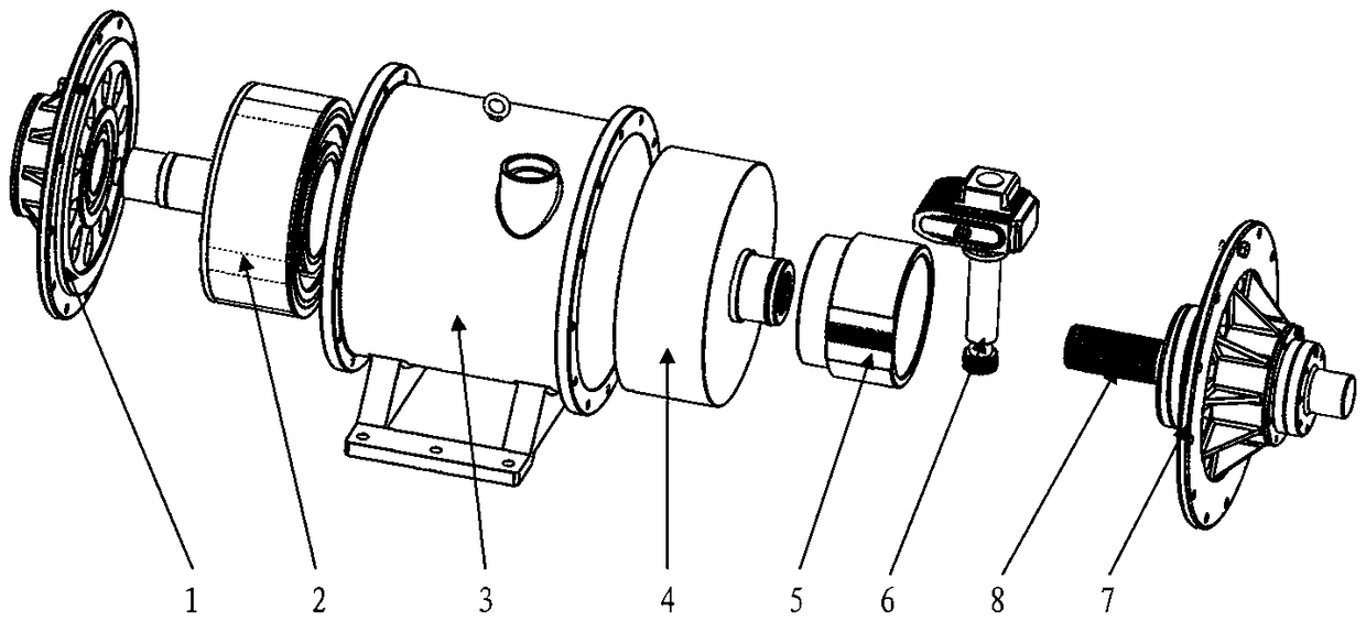
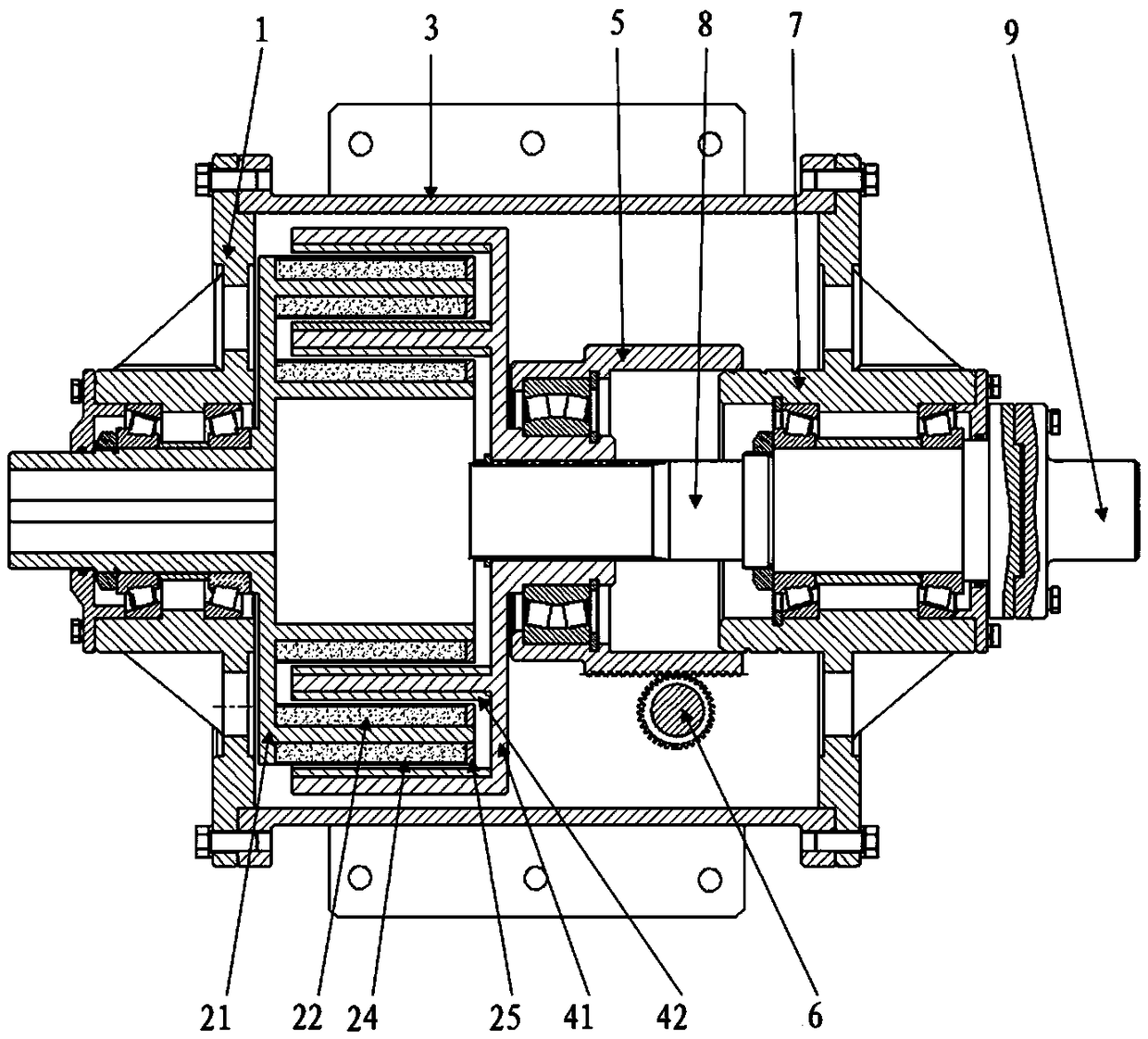
[0053] Magnetic eddy current energy-saving governor, such as figure 1 As shown, it includes a housing assembly 3, a permanent magnet rotor 2 and a conductor rotor 4 that are arranged in the housing assembly 3 and are coupled to each other; the conductor rotor 4 is provided with a sliding part 5 for the axial linear movement of the conductor rotor 4, The sliding part 5 is also connected with a control part 6 for controlling the sliding position of the sliding part 5; the permanent magnet rotor 2 is mounted on the shell assembly 3 through a tapered roller bearing, and the conductor rotor 4 is mounted on the involute spline shaft 8 on the housing assembly 3, and the involute spline shaft 8 is connected to the housing assembly 3 through a tapered roller bearing.

[0054] In the present invention, there is no mechanical connection between the permanent magnet rotor 2 and the conductor rotor 4, one end of the permanent magnet rotor 2 is connected to the motor, one end of the conduc...

Embodiment 2

[0059] The difference between this embodiment and Embodiment 1 is that this embodiment optimizes the structure of the permanent magnet rotor 2 and the conductor rotor 4, and the specific settings are as follows:

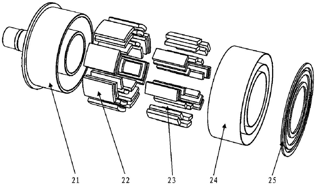
[0060] The permanent magnet rotor 2 includes a permanent magnet rotor base 21 , a magnetic steel mounting ring, a fan-shaped magnetic steel 22 , an envelope 24 , a pressure ring 25 and a spacer 23 .

[0061] In this embodiment, the permanent magnet rotor base body 21 mainly serves as a bearing support for stably fixing the fan-shaped magnetic steel 22 in the housing assembly 3; the magnetic steel mounting ring is fixed on the permanent magnet rotor base body 21, which is mainly It is used to install and fix the sector magnet 22; the main function of the sector magnet 22 is to form an alternating magnetic field and form an eddy current when the conductor is cut; Effect on the magnetic steel mounting ring.

[0062] In the present invention, the number of the magnetic ...

Embodiment 3

[0066] The difference between this embodiment and Embodiment 2 is that in this embodiment, in order to increase the degree of stability, the connection relationship between the permanent magnet rotor 2 and the conductor rotor 4 and the housing assembly 3 is optimized, and the specific settings are as follows:

[0067] The permanent magnet rotor 2 is fixedly connected to the housing assembly 3 through the front end cover 1 , and the sliding part 5 is fixedly connected to the housing assembly 3 through the rear end cover 7 .

[0068] That is, the outer end of the front end cover 1 is fixedly connected with the housing assembly 3 through screws, and the inner end of the front end cover 1 is assembled on the permanent magnet rotor base 21 through tapered roller bearings. The outer end of the rear end cover 7 is fixedly connected with the housing assembly 3 through screws, and the inner end of the rear end cover 7 is assembled and fixed on the involute spline shaft 8 through a taper...


PUM


Abstract

The invention discloses a magnet vortex energy saving speed controller. The problems that in the prior art, a speed controlling device is unstable in speed, low in adjusting precision, inconvenient to maintain and large in size are mainly solved. The magnet vortex energy saving speed controller comprises a shell assembly (3), a permanent magnet rotor (2) and a conductor rotor (4), and the permanent magnet rotor (2) and the conductor rotor (4) are arranged in the shell assembly (3) and coupled to each other. A sliding component (5) used for driving the conductor rotor (4) to do axial linear movement is arranged on the conductor rotor (4), and connected with a control component (6) controlling the sliding position of the sliding component (5). The permanent magnet rotor (2) is arranged on the shell assembly (3) through a conical roller bearing, the conductor rotor (4) is arranged on the shell assembly (3) through an involute spline shaft (8), and the involute spline shaft (8) is connected with the shell assembly (3) through a conical roller bearing. The magnet vortex energy saving speed controller has the advantages of being stable, precise and easy and convenient to maintain, saving energy and the like.

Description

technical field [0001] The invention relates to a governor, in particular to a magnetic eddy current energy-saving governor. Background technique [0002] At present, the commonly used speed regulating devices in the industry include frequency converters and speed regulating hydraulic couplings. [0003] The frequency converter realizes motor speed regulation by changing the current frequency input by the motor. The specific method is: the frequency converter adopts silicon controlled rectification input, and realizes output frequency conversion through PWM DC chopping. This method will generate a large harmonic current, which will seriously pollute the power grid, and can produce fatal electric erosion of the bearing current of the bearing and accelerate bearing damage; at the same time, high-order harmonics will destroy the insulation of the motor, thereby making the motor and load life is reduced. Moreover, the harmonic current will cause heat loss of electrical compone...

Claims


Application Information

Patent Timeline
Patent Type & Authority Patents(China)
IPC IPC(8): H02K51/00
Inventor 魏稼丰冯春安董兴亮杨维清
Owner 四川易尚天交实业有限公司
Why Eureka
Try Eureka