MR receive coil localization and MR-based attenuation correction

A technology of receiving coil and attenuation map, applied in the field of medical imaging, can solve the problem that metal does not generate resonance signal, etc.

Active Publication Date: 2015-06-24
KONINKLJIJKE PHILIPS NV
View PDF2 Cites 7 Cited by
  • Summary
  • Abstract
  • Description
  • Claims
  • Application Information

AI Technical Summary

Problems solved by technology

One challenge of MR-based attenuation correction is that metals do not generate useful resonance signals

Method used


Image

  • MR receive coil localization and MR-based attenuation correction
  • MR receive coil localization and MR-based attenuation correction
  • MR receive coil localization and MR-based attenuation correction

Examples


Embodiment Construction

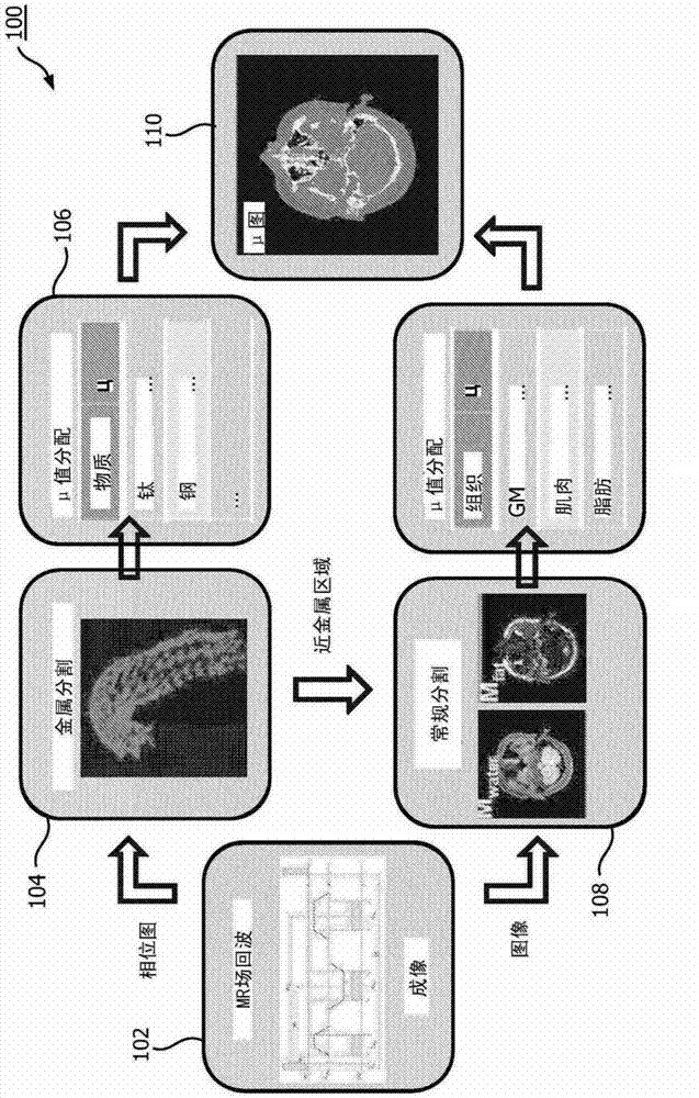
[0021] The present application provides a means to extract the location of magnetic resonance (MR) receive coil hardware from available MR data, for example by using complex MR image phases to detect and locate metal in the MR coil. In addition, the present application provides a means of using complex image phases to locate metal (eg, metal in an MR receive coil or other metal) in an MR examination region.

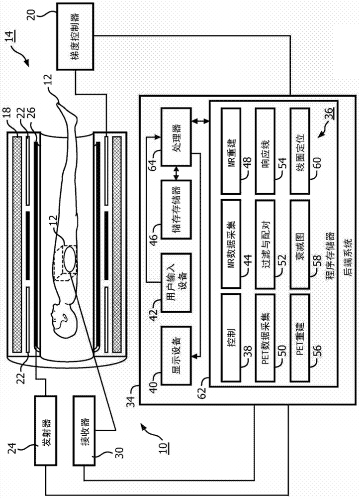
[0022] refer to figure 1 , a combined positron emission tomography (PET) and magnetic resonance (MR) system 10 employs MR and / or PET to image a region of interest (ROI) of a patient 12 . The system 10 includes a scanner 14 that defines (indicated in phantom) an imaging volume 16 that is sized to accommodate the ROI. The size of the imaging volume 16 may vary depending on whether MR or PET is used. A patient support may be used to support the patient 12 in the scanner 14 and to help position the ROI in the imaging volume 16 .

[0023] For MR imaging, the scanner 14 incl...


PUM


Abstract

A system (10) and method generate one or more MR data sets of an imaging volume (16) using an MR scanner (14). The imaging volume (16) includes one or more of a region of interest (ROI), the ROI including a metal element, and a local receive coil (18) of the MR scanner (14). At least one of an attenuation, confidence or density map accounting for the metal element is generated and the location of the local receive coil (18) within the imaging volume (16) is determined. The generating includes identification of the metal element within the ROI based on a phase map of the ROI generated from the MR data sets. The determining includes registering a known sensitivity profile of the local receive coil (18) to a sensitivity map of the local receive coil (18) generated from the MR data sets.

Description

technical field [0001] This application relates generally to medical imaging. It finds particular application in connection with, and will be described with particular reference to, magnetic resonance (MR) based attenuation correction for nuclear medicine (NM) . However, it should be understood that the present application is also applicable to other usage scenarios, and is not necessarily limited to the aforementioned applications. Background technique [0002] In NM imaging modalities such as positron emission tomography (PET) and single photon emission computed tomography (SPECT) systems, attenuation is due to the loss of detection events in the body that absorb or scatter out of the detector field of view. Loss of detected events due to attenuation increases image noise, image artifacts, and image distortion. This in turn affects downstream applications of images generated using PET or SPECT, such as radiation therapy planning. Attenuation is especially problematic i...

Claims


Application Information

Patent Timeline
Patent Type & Authority Applications(China)
IPC IPC(8): A61B6/03A61B6/00A61B5/055G01R33/48G01R33/56G01T1/16G01R33/565
CPCA61B6/037A61B6/4417A61B6/5247A61B6/5258G01R33/481G01R33/5608G01T1/1603G01R33/4828G01R33/5616A61B5/06A61B5/0035A61B6/501A61B5/055A61N5/1039G01R33/287
Inventor C·施特宁S·雷尼施H·达恩克Z·胡
Owner KONINKLJIJKE PHILIPS NV
Why Eureka
Try Eureka