Self-energized bladder pacemaker

A pacemaker, self-powered technology, applied in the field of medical devices, can solve problems such as fear and anxiety, surgical battery replacement, patient pain, etc., and achieve the effect of small size

Inactive Publication Date: 2015-07-01
SECOND MILITARY MEDICAL UNIV OF THE PEOPLES LIBERATION ARMY
View PDF4 Cites 2 Cited by
  • Summary
  • Abstract
  • Description
  • Claims
  • Application Information

AI Technical Summary

Problems solved by technology

[0004] However, the battery life of the bladder pacemaker is 5 to 8 years, and the battery must be replaced by surgery after the power is exhausted.
This will not only cause physical pain and psychological fear and anxiety to patients, but also increase the financial burden on patients and their families.

Method used


Image

  • Self-energized bladder pacemaker
  • Self-energized bladder pacemaker
  • Self-energized bladder pacemaker

Examples


specific Embodiment approach ,< Embodiment 1

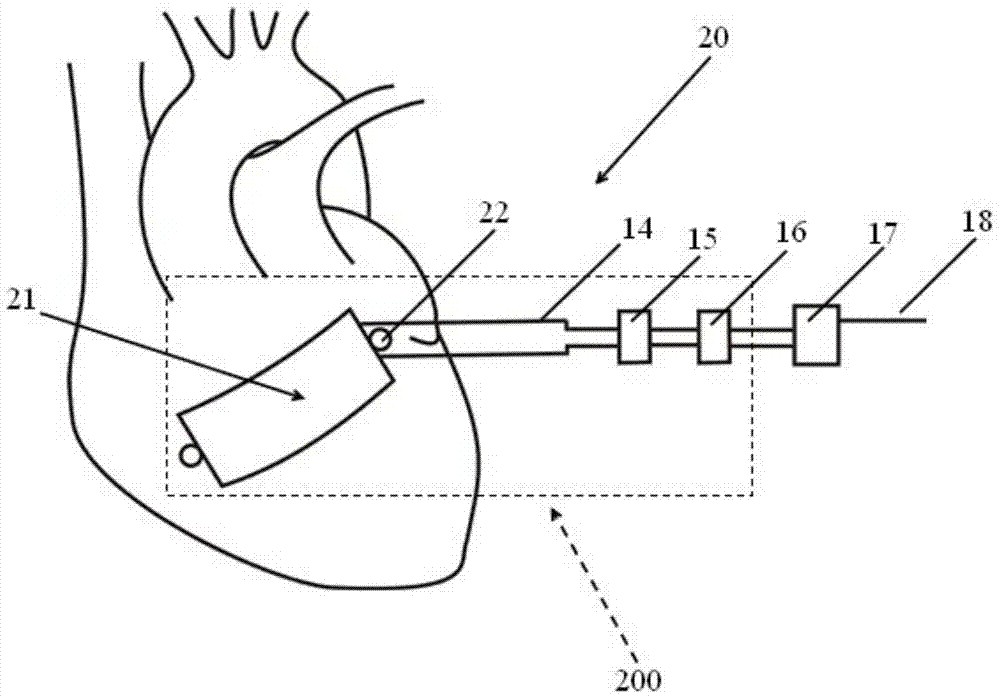
[0025] figure 1 It is a schematic diagram in which the power generating body of the self-powered bladder pacemaker in Example 1 is a quadrilateral, as figure 1 As shown, a self-powered bladder pacemaker 20 has a power generating portion 200 , a pulse generator 17 and stimulating electrodes 18 . Wherein, the power generating unit 200 includes a power generating body 21 , an output unit, an electric energy storage unit 16 , a fixing unit 22 and an encapsulation layer. The generating body 21 is rectangular, and has a fixing unit 22 on each of the two narrow sides of the rectangle, which is used to fix the generating body 11 on the epicardium in the long axis direction along the systolic direction. When the power generating body is implanted, the heart is exposed through surgery, the power generating body is set along the direction of heart contraction and the fixing part is sutured on the epicardium, so that the power generating body and the epicardium fit together. At this time...

Embodiment 2

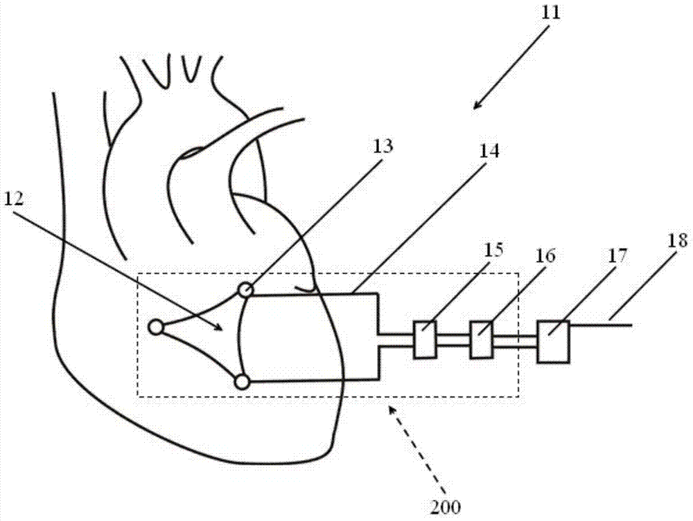
[0031] image 3 It is a schematic diagram of a self-powered bladder pacemaker with a triangular power generation part according to an embodiment of the present invention, as shown in image 3 As shown, the power generation body 12 of the self-powered bladder pacemaker 11 of the present invention is a triangle, and each apex of the triangle has a fixed unit 13, and the output electrode 14 is connected to the electrode layer (see figure 2 ), the rectification and filtering circuit 15 is connected to the output electrode 14 , and the electric energy storage unit 16 is connected to the rectification and filtering circuit 15 to store the electric energy generated by the power generation unit.

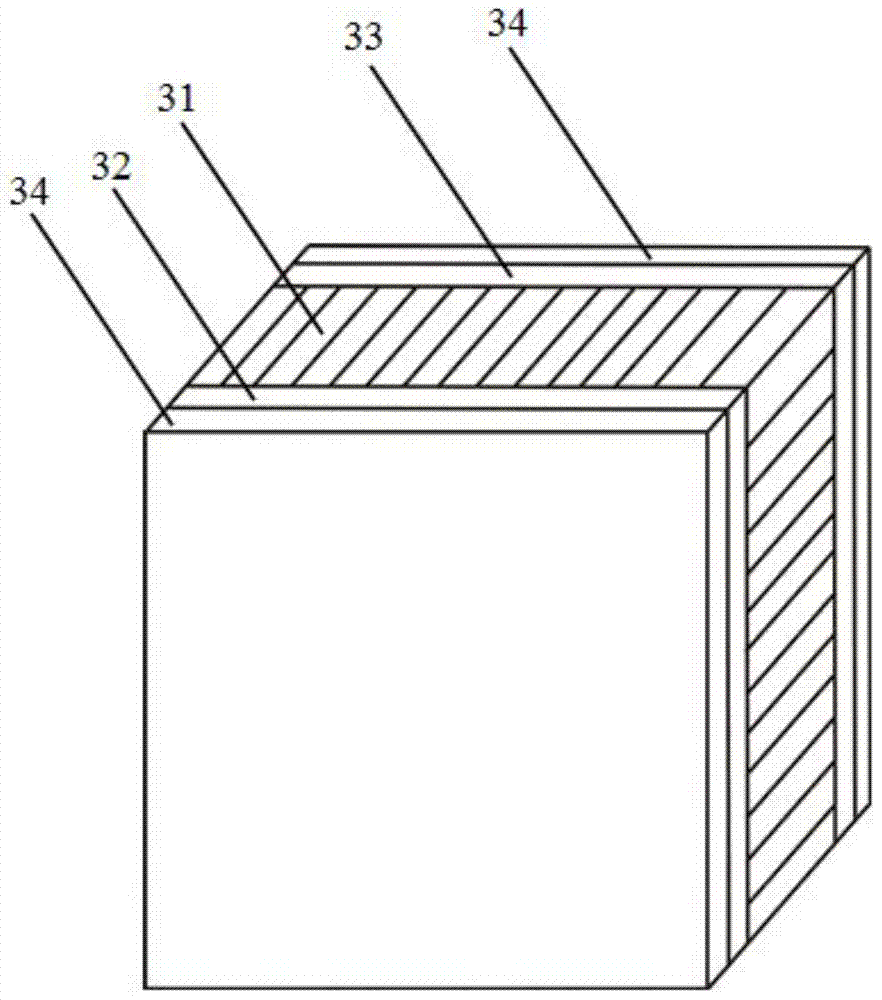
[0032] figure 2 is a cross-sectional view of a self-powered bladder pacemaker according to an embodiment of the present invention, such as figure 2 As shown, the central layer of the power generation body is a piezoelectric material layer 31, and the piezoelectric material layer 31 is c...


PUM


Abstract

The invention provides a self-energized bladder pacemaker, which is characterized by comprising a pulse generator, an exciting electrode, and a power generation portion. The power generation portion comprises a power generation main body, an output unit, an electric energy storage unit, a fixing unit, and a packaged layer. The power generation main body is in a multilayered film structure, comprising a piezoelectric material layer on the center of the power generation main body and electrode layers on two sides of the piezoelectric material layer. The power generation main body is adhered to the surface of a heart to acquire energy of the heart to generate electric energy. The output unit is connected with the electrode layers, and the output unit is used to output current generated by the power generation main body to the electric energy storage unit. The electric energy storage unit is used to store electric energy and supply power for the pulse generator. The fixing unit is on the edge of the power generation main body, and is used to fix the power generation main body on the epicardium. The packaged layer covers the surfaces of the power generation main body, the output unit, the electric energy storage unit, and the fixing unit. The self-energized bladder pacemaker does not need to change batteries, and can be used for whole life.

Description

technical field [0001] The invention relates to a self-powered bladder pacemaker, which belongs to the field of medical devices. Background technique [0002] With the deepening of human understanding of various diseases, more and more diseases can be diagnosed or treated with implanted electronic devices. [0003] Among them, the bladder pacemaker stimulates the sacral nerve, regulates the nerve reflexes of the bladder, sphincter and pelvic floor related to urination, and restores the balance of abnormal nerve reflexes, thereby effectively controlling the symptoms of voiding dysfunction. It can be used for patients with urgency urinary incontinence, urinary frequency and urgency syndrome, non-obstructive chronic urinary retention, overactive bladder and interstitial cystitis caused by various diseases. [0004] However, the battery life of the bladder pacemaker is 5 to 8 years, and the battery must be surgically replaced after the power is exhausted. This will not only ca...

Claims


Application Information

Patent Timeline
Patent Type & Authority Applications(China)
IPC IPC(8): A61N1/36H02N2/18
Inventor 张浩曲丹郎希龙徐志云
Owner SECOND MILITARY MEDICAL UNIV OF THE PEOPLES LIBERATION ARMY
Why Eureka
Try Eureka