A cooling device that generates a flat jet stream

A cooling device and jet flow technology, applied in metal processing equipment, metal rolling, manufacturing tools, etc., can solve the problems of slow closing water flow, poor heat resistance, slow opening water flow of the cooling device, etc., to achieve fast cutting response and cooling effect. Good, good heat-proof effect

Active Publication Date: 2016-11-30
BAOSHAN IRON & STEEL CO LTD
View PDF20 Cites 0 Cited by
  • Summary
  • Abstract
  • Description
  • Claims
  • Application Information

AI Technical Summary

Problems solved by technology

[0017] The purpose of the present invention is to provide a cooling device that produces a flat jet stream. When the cooling device is sprayed for cooling, it does not need to fill the entire box with cooling water every time. When the water spraying is stopped, most of the cooling water It is still stored in the box, and there is always half a box of water in the box, which is always in a cooling state, so as to solve the problems of slow opening water flow, slow closing water flow and poor heat resistance of existing cooling devices

Method used


Image

  • A cooling device that generates a flat jet stream
  • A cooling device that generates a flat jet stream
  • A cooling device that generates a flat jet stream

Examples


Embodiment 1

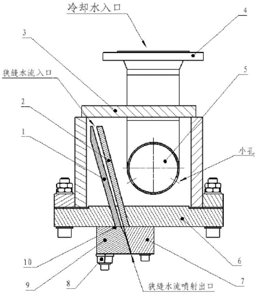
[0046] Such as figure 1 As shown, the cooling device of this embodiment includes: a first drain plate and a second drain plate for forming a drainage channel, a box body, a water inlet pipe assembly, a fixed plate and an adjustable plate for forming a slit, and for adjusting The eccentric bolts with the width of the slit and the temperature-resistant sealing strip used to ensure the watertight sealing of the box.

[0047] In this embodiment, a groove is opened on the lower bottom plate of the box body. The groove is a through groove penetrating the lower bottom plate. The first flow guide plate and the second flow guide plate are embedded on the lower bottom plate of the box body through the groove opened. The lower bottom plate is connected with the side wall of the box by bolts, the first baffle and the second baffle are arranged obliquely, and the drainage channel formed by the first baffle and the second baffle is an inclined gap that gradually narrows from top to bottom. ...

Embodiment 2

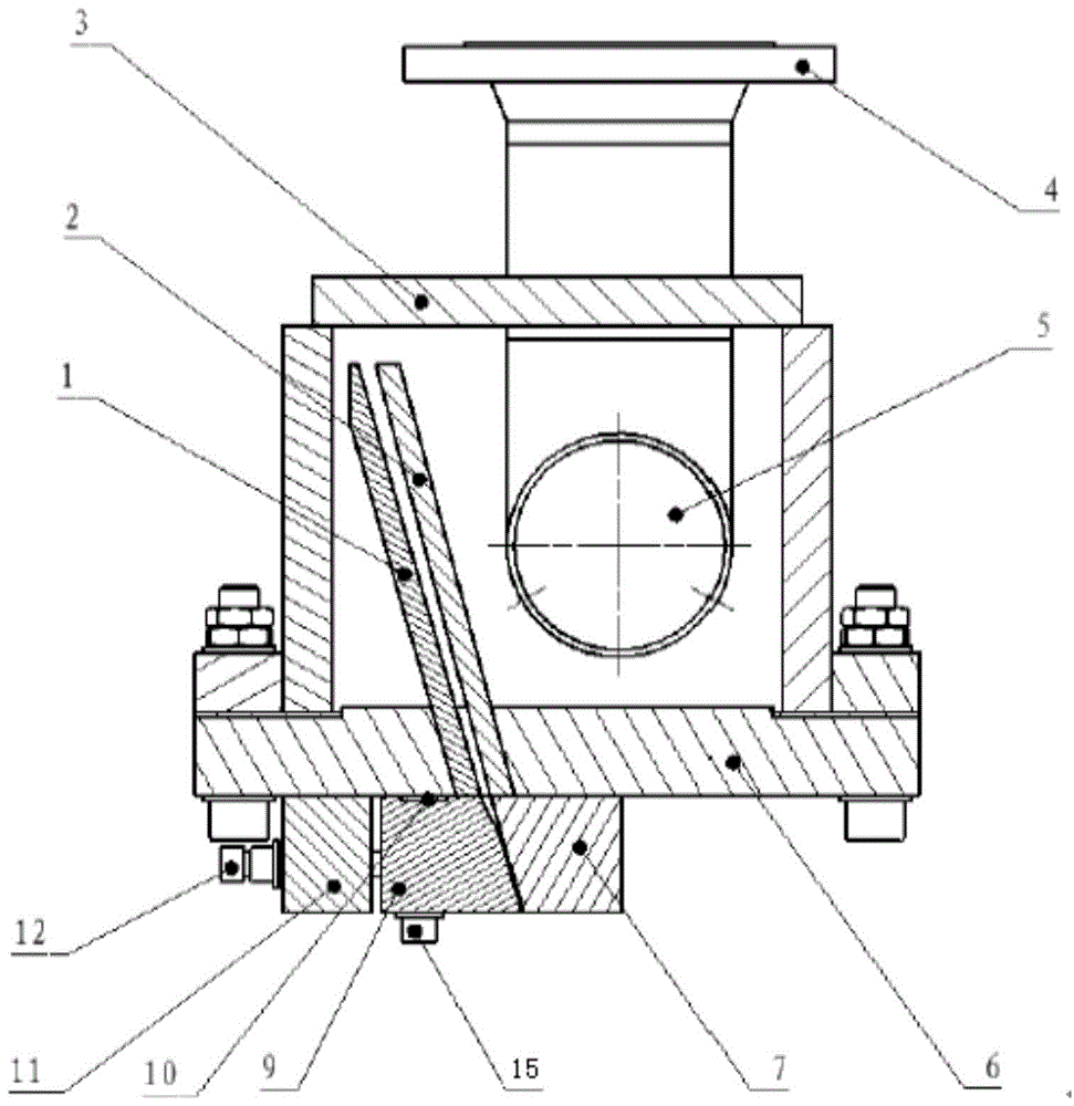
[0056] Such as image 3 The difference between the second embodiment and the first embodiment is that the cooling device of the second embodiment includes a support plate, the support plate is fixedly installed on the lower bottom plate of the box body, and the adjustable plate passes through The first adjusting bolt is installed on the lower bottom plate of the box body, and the support plate is connected with the adjustable plate through the second adjusting bolt.

[0057] This embodiment shows another form of adjustment of the slit width. In this embodiment, the support plate is fixed on the lower bottom plate of the box body, supported by the support plate, and the relative position between the adjustable plate and the fixed plate can be adjusted by tightening or compressing the second adjusting bolt, thereby adjusting Slit width. This embodiment does not need to use eccentric bolts, and the structure is simple and easy to process.

[0058] The present invention adjusts...


PUM


Abstract

The invention relates to a cooling device for generating a flat jet stream, which comprises a tank for storing cooling water and a slit for forming the jet stream, the slit communicates with the tank through a drainage channel arranged inside the tank, and The device also includes a water inlet pipe assembly. The upper end of the water inlet pipe assembly is a cooling water inlet. The cooling water inlet is located directly above the outside of the box. There are many small holes on both sides of the pipe; the upper end of the drainage channel is the jet water inlet, which is located near the top of the box, and the drainage channel is connected with the slit, which is composed of a fixed plate and an adjustable Plate formed with adjustable slit width. The invention solves the problems of slow opening of water flow, slow closing of water flow and poor heat resistance of the existing cooling device.

Description

technical field [0001] The invention relates to the technical field of post-rolling cooling in metal processing, in particular to a cooling device for generating flat jet streams, which is used for post-rolling treatment of hot-rolled strip steel and medium-thick plates. Background technique [0002] At present, with the development and research of advanced steel materials, in order to obtain high value-added and recyclable steel products, ultra-rapid cooling after rolling is an important process to improve the performance of steel materials and realize the development of steel types. play an important role. Due to the high cooling intensity, the slot spray (slit jet) cooling method is more and more used in the field of quenching machines and hot rolling of wide and thick plates that require rapid and strong cooling. [0003] Foreign patents: [0004] LOI THERMPROCESS GmbH(德国洛伊热处理有限公司)的专利族:名称《Deicefor Cooling Material by Producing A Flat Jet》,授权号DE50203689D1、DE20114136、WO0...

Claims


Application Information

Patent Timeline
Patent Type & Authority Patents(China)
IPC IPC(8): B21B45/02
Inventor 朱健桦王笑波张春伟张庆峰刘晔吴建峰
Owner BAOSHAN IRON & STEEL CO LTD
Why Eureka
Try Eureka