
Integrated safe driving device

A safe driving, integrated technology, applied in escalators, transportation and packaging, etc., can solve the problems of cumbersome operation, low installation efficiency, long installation time, etc., to ensure speed detection accuracy, improve installation efficiency, and reduce installation difficulty. Effect

Active Publication Date: 2015-07-01
UNITE ELEVATOR
View PDF5 Cites 6 Cited by
  • Summary
  • Abstract
  • Description
  • Claims
  • Application Information

AI Technical Summary

Problems solved by technology

[0006] (1) Due to the heavy weight of the escalator drive motor, reduction box and main drive shaft, and the vibration of the hoisting equipment itself, the installation is difficult and requires multiple adjustments of their positions. The cumbersome operation leads to high labor intensity for the installers. Installation accuracy difficulty guarantee
[0007] (2) The escalator drive motor, gearbox and main drive shaft need to be hoisted and installed separately, that is, at least three hoisting operations are required to install the above three components, resulting in long installation time and low installation efficiency
[0008] (3) In addition, since the installation of the escalator drive motor, reduction box and main drive shaft is relatively difficult, in order to avoid necessary rework procedures, in the prior art, the escalator drive motor, reduction box and main drive shaft are generally hoisted and installed separately After the installation of the escalator, the position of the escalator must match the drive motor, reduction box and main drive shaft of the escalator; this greatly affects the installation time of the whole elevator
[0009] In addition, the output pump and the output gear of the existing reduction box are generally connected by a simple key. After long-term use, the cooperation between the output shaft of the reduction box and the output gear will become loose, resulting in the failure of the main drive shaft to operate normally.

Method used


Image

  • Integrated safe driving device
  • Integrated safe driving device
  • Integrated safe driving device

Examples


Embodiment Construction

[0085] The specific technical contents and implementation methods of the present invention will be described in detail below in conjunction with the accompanying drawings.

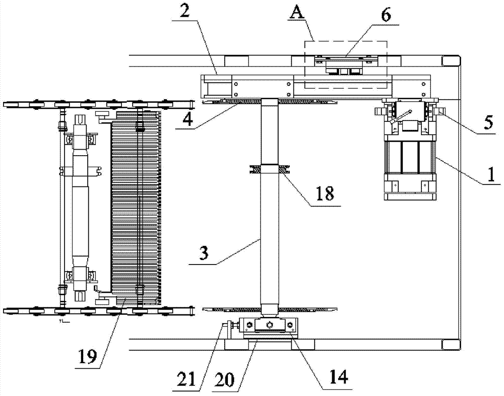
[0086] like figure 2 Shown: an integrated escalator driving device, including a drive motor 1, a reduction box 2, a main drive shaft 3 and a bearing housing 14 that are sequentially transmitted and coordinated. The main drive shaft 3 is provided with a step sprocket 4 and a handrail sprocket 18 , the main shaft of the drive motor 1 is provided with a main brake 5, and at least one intermediate shaft in the reduction box 2 is provided with an additional brake 6.

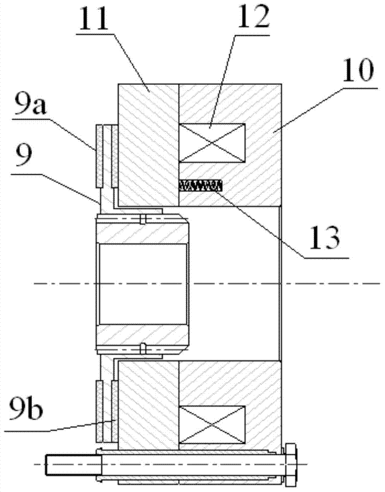
[0087] like image 3 and Figure 4 As shown, the additional brake 6 includes a housing 7, and the housing 7 is provided with: a brake disc 9 fixed on the outer periphery of the intermediate shaft 8; a static friction plate 9a and a dynamic friction plate 9b acting on both sides of the brake disc 9, and a dynamic friction plate acting on the dyn...


PUM


Abstract

The invention discloses an integrated safe driving device. The integrated safe driving device comprises a driving motor, a speed reduction box, a main driving shaft and a bearing seat which are pre-integrated and in sequential transmission fit, wherein the bearing seat is arranged at the end, far away from the speed reduction box, of the main driving shaft, installation positions for being fixed to a truss are arranged at the bottoms of the speed reduction box and the bearing box, and an output gear of the speed reduction box and the main driving shaft are positioned through tightly matched conical surfaces. The invention further provides an installation method of the integrated safe driving device. The driving motor, the speed reduction box, the main driving shaft and the bearing seat are pre-integrated, installation of the driving device is facilitated, installation difficulty is reduced, installation accuracy is improved through matching of the conical surfaces, installation efficiency is guaranteed, and products meet national standards and have large market prospects.

Description

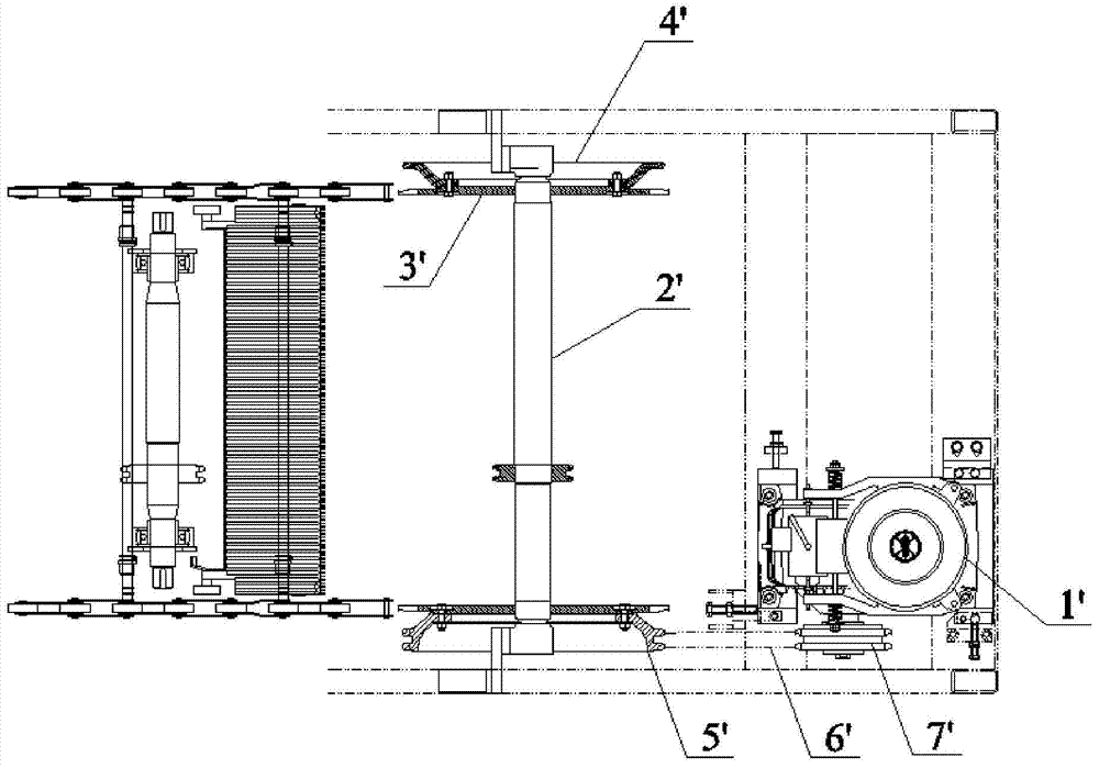
technical field [0001] The invention belongs to the technical field of design of escalator components, and in particular relates to an integrated safety driving device. Background technique [0002] The existing escalator driving device is mainly figure 1 the structure represented, figure 1 Represents the schematic diagram of the top view structure of the escalator drive host in the prior art, through figure 1 The structural features of the prior art can be clearly seen, which mainly includes a drive motor 1', a main drive shaft 2', a step sprocket 3', and an additional brake 4'. The escalator drive motor 1' and the main drive shaft 2' are installed independently, each with a driving wheel 5' and a driven wheel 7', and the transmission of the drive motor 1' to the main drive system is realized by the transmission of the main drive chain 6'. The additional brake 4' includes components such as a driven disc with a block, a friction plate, a brake disc, and a trigger mechani...

Claims


Application Information

Patent Timeline
IPC IPC(8): B66B23/02B66B27/00
CPCB66B23/02B66B29/00B66B29/005
Inventor 陈成强沙潇迪徐国香
Owner UNITE ELEVATOR
Learn More