Ice and snow preventing device of steel track beam

A steel track beam, anti-ice and snow technology, applied in the field of rail transit, can solve the problems of train operation delay, beam structure damage, beam body small cross-section, etc., achieve simple and reasonable structure, ensure normal operation, and have little impact on the structure

Inactive Publication Date: 2015-07-01
CHINA RAILWAY ENG CONSULTING GRP CO LTD
6 Cites 8 Cited by

AI-Extracted Technical Summary

Problems solved by technology

Although this method is relatively simple, the location of the track beams is high, people are more dangerous during the snow removal process, and it takes a certain amount of time to clear the snow, which will still cause delays to train operations
[0006] In addition, the bridge deck heating ice and snow melting technology used in highway bridges is not suitable for steel track girders
Steel track beams have different characteristics from other bridges: the heating area is large, and the top and sides of the beam body need to be snow-r...

Method used

A kind of anti-ice and snow device for steel track beam provided by the present invention adopts that heating cable 4 is set on the top surface of beam body 1 of steel track beam, and anti-ice and snow coating 6 is set on both sides of beam body 1, which can solve the problem of beam Quickly melt ice and snow on the surface and prevent the problem of ice and snow on the side of the beam body 1, ensuring the normal operation of the train without causing train stoppage or delay, and the installation of the anti-ice and snow coating 6 is simple in construction and low in maintenance costs;
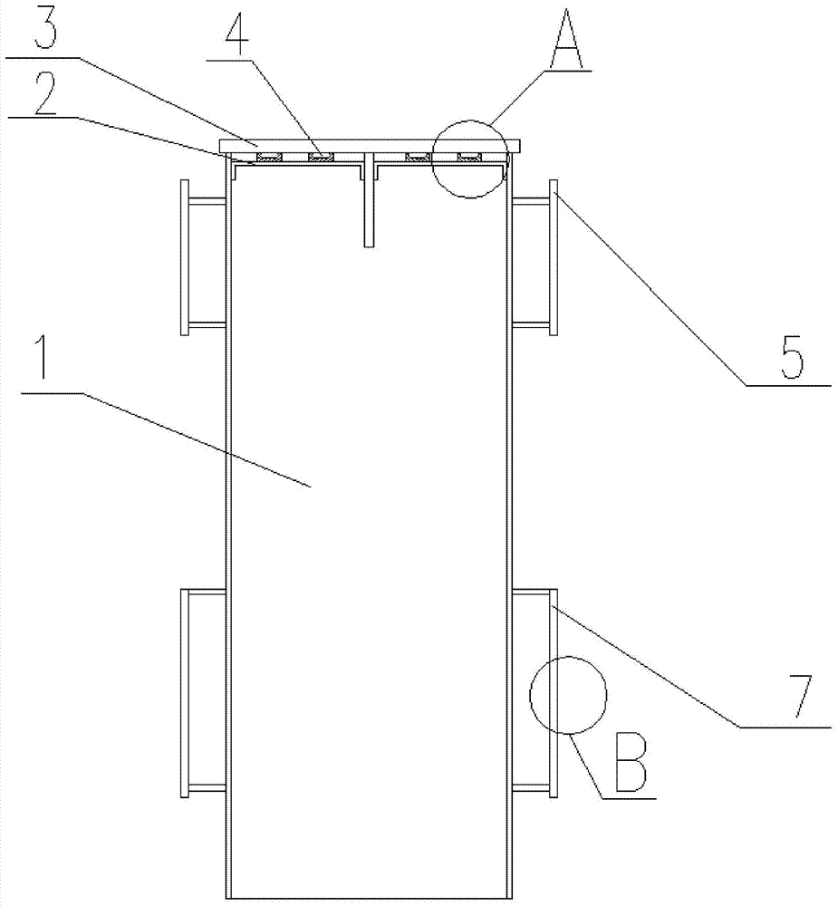
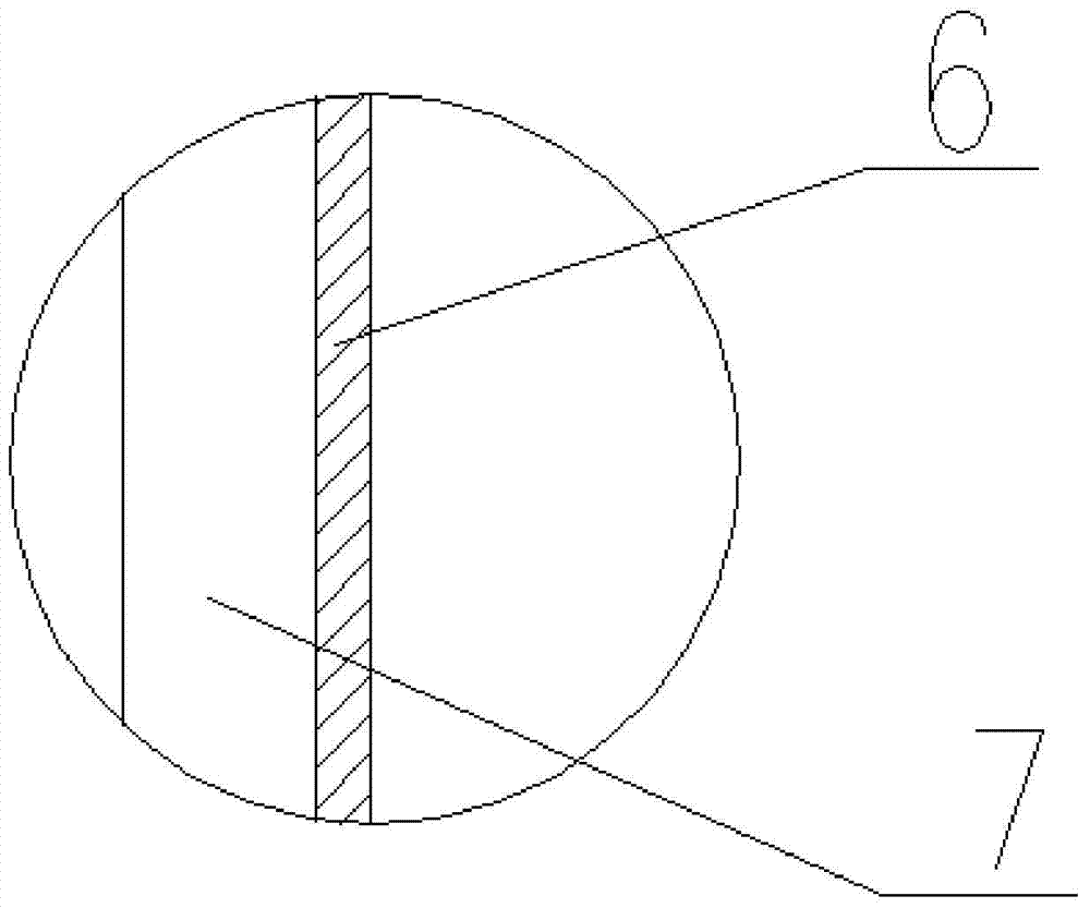
As shown in Fig. 1 and Fig. 3, a kind of anti-ice and snow device for steel track beam provided by the present invention, it comprises the heating cable 4 that is arranged along the beam body 1 top surface of steel track beam and two along the beam body 1 The anti-ice and snow coating 6 provided on the side, the working principle of the heating cable 4 is to convert electrical energy into heat energy, and through direct or indirect heat exchange, it is used to heat the steel plate 3 on the running surface of the beam body 1. The anti-ice and snow coating The layer 6 is used to prevent the steel plate 5 on the guide surface and the steel plate 7 on the stable surface of the beam body 1 from adhering to ice and snow. The combination of the heating cable 4 and the anti-ice and snow coating 6 not only simplifies the construction difficulty, saves the cost, but also can Reach better anti-ice and snow effect, guarantee the normal operation of train; Described anti-ice and snow coating 6 can be a kind of in modified silane impregnating agent and high-pressure tire wear-resistant anti-ice and snow coating, and described modified silane impregnating agent is sprayed on After the concrete surface, a hydrophobic layer can be formed on the concrete surface, which can effectively prevent ice and snow adhesion. The wear-resistant anti-ice and snow coating for high-pressure tires can be automatically cured at room temperature, and a dry coating film of more than 1 mm can be formed on the protective surface, which can prevent ice and snow adhesion. At the same time, it has the advantages of high...

Abstract

The invention relates to the technical field of track traffic, and discloses an ice and snow preventing device of a steel track beam. The ice and snow preventing device comprises heat tracking belts and ice and snow preventing coatings, wherein the heat tracing belts are arranged on the top face of a beam body of the steel track beam, and the ice and snow preventing coatings are arranged on the two side faces of the beam body; the heat tracing belts are used for heating walking face steel plates of the beam body; and the snow preventing coatings are used for preventing ice and snow from being attached to guide face steel plates and stabilizing face steel plates of the beam body. The heat tracing belts are attached to the lower side of the walking face steel plate, and remaining portions of the heat tracking belts are wrapped by a heat insulation layer; and the heat insulation layer is used for reducing heat losses and preventing heat from being transmitted to the interior of the beam body. According to the device, whole-line ice and snow melting of the steel track beam can be rapidly carried out, large temperature stress cannot be generated, safety performance of the device is ensured, and the construction difficulty is simplified.

Application Domain

Technology Topic

Image

  • Ice and snow preventing device of steel track beam
  • Ice and snow preventing device of steel track beam
  • Ice and snow preventing device of steel track beam

Examples

  • Experimental program(1)

Example Embodiment

[0029] The specific embodiments of the present invention will be described in further detail below in conjunction with the drawings and embodiments. The following examples are used to illustrate the present invention, but not to limit the scope of the present invention.
[0030] In the description of the present invention, it should be noted that the terms "center", "longitudinal", "transverse", "upper", "lower", "front", "rear", "left", "right", " The orientation or positional relationship indicated by "vertical", "horizontal", "top", "bottom", "inner", "outer", etc. are based on the orientation or positional relationship shown in the drawings, and are only for the convenience of describing the present invention and simplifying The description does not indicate or imply that the pointed device or element must have a specific orientation, be configured and operated in a specific orientation, and therefore cannot be understood as a limitation of the present invention.
[0031] Such as figure 1 with image 3 Shown here is an anti-icing device for a steel track beam provided by the present invention, which includes a heating cable 4 arranged along the top surface of the beam body 1 of the steel track beam and an anti-icing and snow coating 6 arranged along the two sides of the beam body 1. The working principle of the heating cable 4 is to convert electric energy into heat energy, which is used to heat the running surface steel plate 3 of the beam body 1 through direct or indirect heat exchange, and the anti-icing and snow coating 6 is used to prevent the beam body 1 from being damaged. The guide surface steel plate 5 and the stable surface steel plate 7 are attached to ice and snow. The combination of the heating cable 4 and the anti-icing and snow coating 6 not only simplifies the construction difficulty, saves the cost, but also achieves a better anti-icing effect and guarantees The normal operation of the train; the anti-icing and snow coating 6 can be one of a modified silane impregnant and a high-pressure tire wear-resistant and anti-icing and snow coating. After the modified silane impregnant is sprayed on the surface of the concrete, it can form on the surface of the concrete The water-repellent layer can effectively prevent the adhesion of ice and snow. The high-pressure tire wear-resistant and anti-icing and snow coating can automatically cure at room temperature to form a dry film of more than 1 mm on the protective surface, which can prevent ice and snow adhesion, and has high pressure resistance, impact resistance, and shock resistance. It has the advantages of dynamic, corrosion resistance and aging resistance, and can effectively prevent the sliding of the wheel and the track surface.
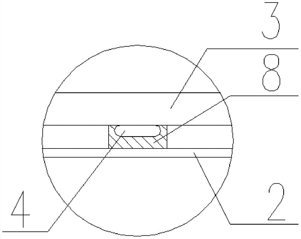
[0032] Such as figure 2 As shown, the heating cable 4 is attached to the underside of the running surface steel plate 3, and the remaining part is wrapped with an insulating layer 8, which is used to reduce heat loss and transfer to the inside of the beam 1, because the thermal conductivity of the steel is relatively large. When the heating cable 4 is energized and heated, the heat can be directly transferred to the surface of the beam 1, which enhances the heat conduction with the steel plate of the beam 1, can quickly melt the ice and snow on the road surface, and can increase the heating speed of the surface of the beam 1. , It can reduce the temperature gradient of the beam 1 and reduce the temperature difference stress.
[0033] Such as figure 1 with Figure 4 As shown, the heating cable 4 is fixed on the lower side of the running surface steel plate 3 by a plurality of fixed steel plates 2 arranged at intervals. Preferably, the fixed steel plate 2 is welded to the running surface steel plate 3, and the beam body 1 There is a steel support beam arranged along the length of the track beam in the center below the top surface of the steel plate, two ends of the fixed steel plate 2 are provided with downwardly extending support plates, and the fixed steel plates 2 are respectively installed on the support beam In the two parts of the space formed by the two sides and the two sides of the beam body 1, one side support plate of the fixed steel plate 2 is welded to the side surface of the beam body 1, and the other side support plate is welded to one side of the support beam. The thermal insulation layer 8 and the heating cable 4 need to be clamped tightly when the steel plate 2 is installed. The thermal insulation layer 8 is fixedly connected to the fixed steel plate 2 by bolts or screws and other connecting parts. When the heating cable 4 needs to be overhauled, it can be installed at intervals The gap between the fixed steel plates 2 is inspected or repaired, or the heating cable 4 is extracted from the end of the steel track beam along the surface of the thermal insulation layer 8 for inspection or replacement.
[0034] The heating cable 4 includes a plurality of heating conductors arranged side by side. According to the demand of heat and the arrangement of the structure, the number of the heating conductors is preferably six, and each heating conductor is wrapped with an insulating protective sleeve. The insulating protective sleeve It may include two layers, the first layer is a fluoropolymer protective layer, and the second layer is a silica gel protective layer to achieve a reliable insulation protection effect; a plurality of the heating conductors are provided with thermal insulation jackets, the thermal insulation jackets It is preferably a glass fiber thermal insulation jacket, which can further reduce the loss of heat to the surrounding environment.
[0035] A plurality of the heating conductors are connected in series, so that it has an extremely long heating circuit, and the entire heating cable 4 has no cold spots, and no voltage drop will cause power loss.
[0036] The heating cable 4 is flat, which can increase its contact area with the track surface, so it can transmit the maximum heat to the track. When multiple heating cables 4 are arranged side by side, it is necessary to ensure that there is a space between each heating cable 4 A certain insulation distance is required to avoid overheating caused by heat accumulation, which may cause danger.
[0037] In addition, the ice and snow melting device also includes a monitoring system, the monitoring system includes one or more control cabinets set at the remote site of the steel track beam, used to automatically switch off the station according to the temperature monitored by the weather and whether there is rain or snow. As for the heating cable 4, the parameters of the monitoring system are set according to the parameters actually measured by one or more weather stations. The weather station measures temperature, wind speed and monitors whether there is rain or snow, in a complete monitoring system Even multiple weather stations or multiple temperature sensors can be connected. The control cabinet is not only used to distribute heat, but also to monitor the entire system and detect errors.
[0038] The present invention provides an anti-icing and snow device for steel track beams. The heating cable 4 is arranged on the top surface of the beam body 1 of the steel track beam, and the anti-icing and snow coating 6 is arranged on both sides of the beam body 1, which can solve the problem of rapid melting of the beam surface. Ice and snow and prevent the problem of ice and snow adhesion on the side of the beam 1 to ensure the normal operation of the train without causing the train to stop or delay, and the installation of the anti-icing coating 6 is simple in construction and low in maintenance costs;
[0039] The heating cable 4 is attached to the running surface steel plate 3, and the remaining part is wrapped with an insulating layer 8, which can reduce the heat loss and transfer to the inside of the beam 1, which can increase the heating speed on the surface of the beam 1 and reduce the beam The temperature gradient of body 1 reduces the temperature difference stress;
[0040] The ice and snow melting device has a simple and reasonable structure, has little impact on the structure of the steel track beam, is convenient to construct, and ensures the normal operation of the steel track beam in the ice and snow climate, and has obvious social and economic benefits.
[0041] The above descriptions are only preferred embodiments of the present invention and are not intended to limit the present invention. Any modification, equivalent replacement, improvement, etc. made within the spirit and principle of the present invention shall be included in the present invention. Within the scope of protection.

PUM

no PUM

Description & Claims & Application Information

We can also present the details of the Description, Claims and Application information to help users get a comprehensive understanding of the technical details of the patent, such as background art, summary of invention, brief description of drawings, description of embodiments, and other original content. On the other hand, users can also determine the specific scope of protection of the technology through the list of claims; as well as understand the changes in the life cycle of the technology with the presentation of the patent timeline. Login to view more.

Similar technology patents

Wrench for butterfly nut

InactiveCN104191399AImprove locking forceGuarantee normal operationSpannersWrenchesWrenchEngineering
Owner:YANCHENG BAODING POWER TOOLS

Classification and recommendation of technical efficacy words

  • Simple construction
  • Guarantee normal operation

Illumination system for microlithography

ActiveUS20060050261A1Transmission efficiency be highSimple constructionPhotomechanical apparatusPhotographic printingSpatially resolvedLighting system
Owner:CARL ZEISS SMT GMBH
Why Eureka
Try Eureka