Anti-floating device for tunnel construction, steel mould board lining rig and anti-floating construction method

A technology for tunnel construction and lining of trolleys, which is applied in tunnel lining, tunnel, shaft lining and other directions, can solve problems such as low construction efficiency, heavy trolley weight, complex structure, etc., and achieves improved construction efficiency, good lining effect, and anti-floating. good performance

Active Publication Date: 2015-07-01
SHANDONG LUQIAO GROUP
View PDF11 Cites 9 Cited by
  • Summary
  • Abstract
  • Description
  • Claims
  • Application Information

AI Technical Summary

Problems solved by technology

The floating of the trolley will cause virtual connection or separation between the portal frame and the track. When the virtual connection occurs, the portal frame will be displaced relative to the lining formwork, the formwork will be deformed, and the geometric dimensions of the lining will be deviated, resulting in permanent quality defects. When detached, the lining trolley will be unstable. , collapsed, causing damage to the trolley, scrapping the poured concrete and even causing casualties
[0003] There are two anti-floating methods for lining trolleys in the prior art. One is the traditional method of increasing the self-weight of the trolley to overcome the buoyancy force of the concrete; the other is to design a special anti-floating mechanism, such as the Chinese patent CN202718678U proposes a full-circle tunnel needle beam trolley with an anti-floating mechanism. The anti-floating mechanism

Method used


Image

  • Anti-floating device for tunnel construction, steel mould board lining rig and anti-floating construction method
  • Anti-floating device for tunnel construction, steel mould board lining rig and anti-floating construction method
  • Anti-floating device for tunnel construction, steel mould board lining rig and anti-floating construction method

Examples


Embodiment Construction

[0027] The present invention will be further clearly and completely described in conjunction with the accompanying drawings in the embodiments of the present invention, and the described embodiments are only some of the embodiments of the present invention, not all of them.

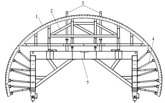
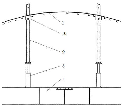
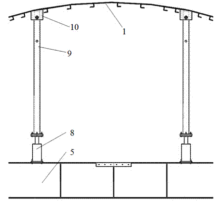
[0028] Reference attached Figure 5 , Image 6 , an anti-floating device for tunnel construction, comprising an anti-floating column 9, a lifting cylinder 8 and a limit mechanism 10, the lower end of the anti-floating column 9 is connected to the trolley door frame 5 of the steel mold lining trolley through the lifting cylinder 8, and the anti-floating column 9 The upper part is provided with a plurality of limit holes 12 in the axial direction, and the limit mechanism 10 includes a limit installation body 18 and a limit pin 16, wherein the limit installation body 18 is installed on the trolley template 1 of the steel mold lining trolley, and the limit The position mounting body 18 is provided with a ...


PUM


Abstract

The invention provides an anti-floating device for tunnel construction, a steel mould board lining rig and an anti-floating construction method. The device comprises an anti-floating column, a lifting cylinder and a lifting mechanism, wherein the lower end of the anti-floating column is connected to a door frame of the steel mould board lining rig through the lifting cylinder; a plurality of limiting holes are axially formed in the upper part of the anti-floating column; the limiting mechanism comprises a limiting mounting body and a limiting pin, wherein the limiting mounting body is mounted at a mould board of the steel mould board liming rig; a limiting mounting through hole is formed in the limiting mounting body; the limiting pin passes through a limiting pin mounting hole and is in match with the limiting holes in the anti-floating column. The device is high in anti-floating performance, simple in structure, convenient to mount, good in lining effect, and high in construction efficiency.

Description

technical field [0001] The invention belongs to the technical field of engineering machinery, and in particular relates to an anti-floating device for tunnel construction, a steel mold lining trolley and an anti-floating construction method. Background technique [0002] The steel formwork lining trolley is special equipment that must be used in the secondary lining of the tunnel construction process. It is used for the concrete lining construction of the inner wall of the tunnel. Affected by the buoyancy generated by the concrete, when the buoyancy is greater than the self-weight of the trolley, the steel formwork and the trolley as a whole will float and deform. The floating of the trolley will cause virtual connection or separation between the portal frame and the track. When the virtual connection occurs, the portal frame will be displaced relative to the lining formwork, the formwork will be deformed, and the geometric dimensions of the lining will be deviated, resu...

Claims


Application Information

Patent Timeline
IPC IPC(8): E21D11/10
CPCE21D11/10E21D11/102
Inventor 王兴阔白宾王殿学韩军霞刘颖张文哲
Owner SHANDONG LUQIAO GROUP
Why Eureka
Try Eureka