Compressor pre-rotation control method

A compressor and pre-rotation technology, which is applied in the direction of engine control, electrical control, mechanical equipment, etc., can solve problems such as limiting the driving conditions of the compressor, and achieve the effect of increasing the maximum speed and improving durability

Active Publication Date: 2019-05-03
VOLVO CAR CORP
View PDF5 Cites 0 Cited by
  • Summary
  • Abstract
  • Description
  • Claims
  • Application Information

AI Technical Summary

Problems solved by technology

This severely limits the driving conditions that allow the use of compressors

Method used


Image

  • Compressor pre-rotation control method
  • Compressor pre-rotation control method
  • Compressor pre-rotation control method

Examples


Embodiment Construction

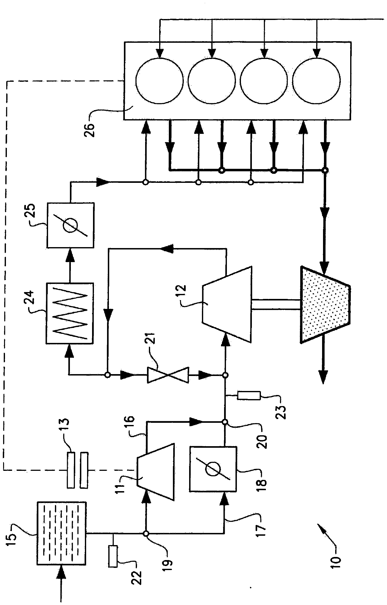
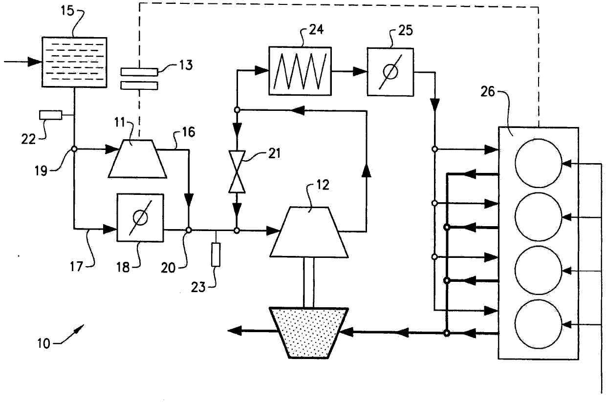
[0054] figure 1 A schematic diagram of a preferred embodiment of an internal combustion engine 10 with a compressor 11 and a turbocharger 12 is shown. The compressor 11 is connected to the crankshaft of the internal combustion engine 10 via a compressor clutch 13 . By engaging and disengaging the compressor clutch 13 , the compressor 11 can be directly or indirectly engaged and disengaged from the crankshaft of the internal combustion engine 10 , respectively. When the compressor 11 is engaged with the crankshaft of the internal combustion engine 10 , the crankshaft drives the compressor 11 . The compressor 11 increases the air pressure or air density so that more air (ie more oxygen) is supplied to the combustion chambers of the internal combustion engine 10 . The increased amount of air allows more fuel to be injected, allowing more power to be produced.

[0055] As previously stated, traditionally, when the compressor clutch is engaged, the compressor rotates significant...


PUM


Abstract

A compressor (11) is connected via a clutch (13) to a crankshaft of an internal combustion engine provided with a turbocharger (12). A compressor pre-spin operation is used to reduce the transferred energy and wear when the clutch is engaged. The pre-spin is achieved by controlling the air mass flow over the compressor, wherein the air mass flow over the compressor is controlled by controlling a bypass throttle angle of a bypass throttle (18) provided in a bypass conduit (17) bypassing the compressor.

Description

technical field [0001] The invention relates to a method of controlling the pre-rotation operation of a compressor of an internal combustion engine. When the compressor clutch is engaged, the wear on the clutch is proportional to the energy transferred. To reduce compressor clutch wear or increase the maximum engine speed allowed to engage the compressor, compressor pre-rotation is utilized when the clutch is engaged to reduce the amount of energy transferred. Background technique [0002] In order to increase the pressure and air density of the air supplied to the internal combustion engine, the use of compressors or superchargers is a known method. The increased amount of air provides more oxygen in each working cycle, which enables an increased amount of fuel to be injected, allowing the engine to generate more power. [0003] When the compressor clutch is engaged, the speed of the compressor is generally low, and the speed of the crankshaft, which is engaged with the c...

Claims


Application Information

Patent Timeline
Patent Type & Authority Patents(China)
IPC IPC(8): F02B39/16F02B39/12F02B39/04
CPCF02B37/04F02B37/162F02B39/12F02B2037/125F02D23/005F02D41/0007F02D41/18F02D2009/0279F02D2009/0283F02D2200/0402F02D2200/0406F02D2200/0414Y02T10/12F02B37/12F02B37/16
Inventor J·斯文松M·卡伦
Owner VOLVO CAR CORP
Why Eureka
Try Eureka