Rotary compressor and refrigeration cycle device

A technology of a rotary compressor and a compression mechanism, applied to a rotary piston type/oscillating piston type pump component, a rotary piston type/oscillating piston type pump combination for an elastic fluid, and a component of a pumping device for an elastic fluid Equal direction, to achieve the effect of strong interchangeability, stable angular velocity and simple structure

Inactive Publication Date: 2017-06-06
GUANGDONG MEIZHI COMPRESSOR
View PDF5 Cites 0 Cited by
  • Summary
  • Abstract
  • Description
  • Claims
  • Application Information

AI Technical Summary

Problems solved by technology

[0004] For this reason, the present invention proposes a rotary compressor, the angular velocity of the rotor can be stabilized by the torque buffering effect of the torsion bar spring, and the problem of motor efficiency reduction will not occur

Method used


Image

  • Rotary compressor and refrigeration cycle device
  • Rotary compressor and refrigeration cycle device
  • Rotary compressor and refrigeration cycle device

Examples


Embodiment 1

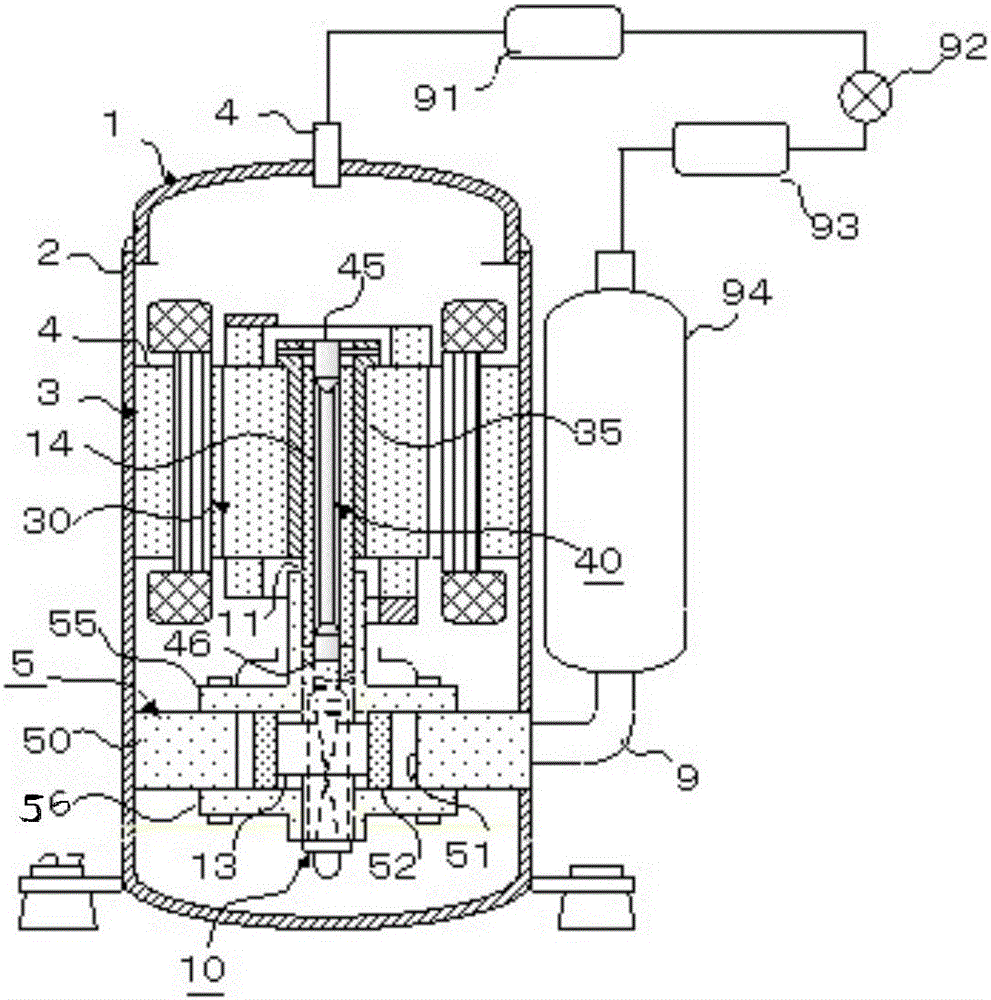
[0057] This embodiment is an application example of a single-cylinder rotary compressor using a single-phase induction motor. figure 1 The configurations of the rotary compressor 1 and the refrigeration cycle are shown.

[0058] The rotary compressor 1 is composed of a compression mechanism 5 fixed on a sealed cylindrical casing 2 , a motor 3 arranged on top of it, and a stator 4 fixed on the casing 2 . Therefore, the compression mechanism 5 is driven by the rotational moment of the rotor 30 generated between the stator 4 and the stator 4 . In addition, lubricating oil (not shown) is stored in the bottom of the casing 2 .

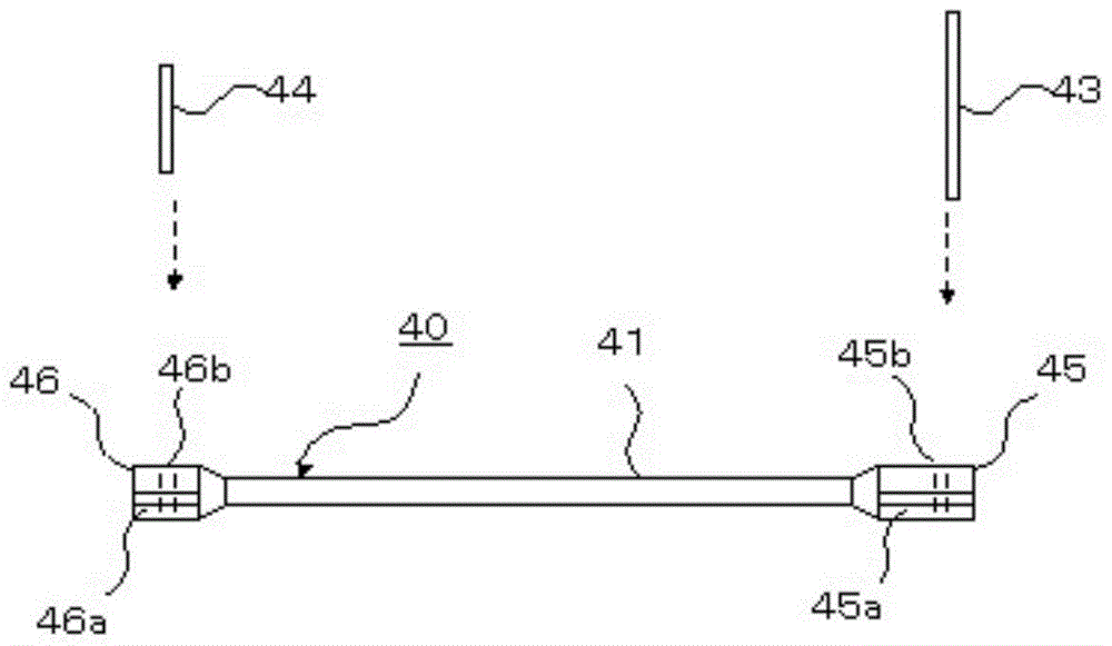
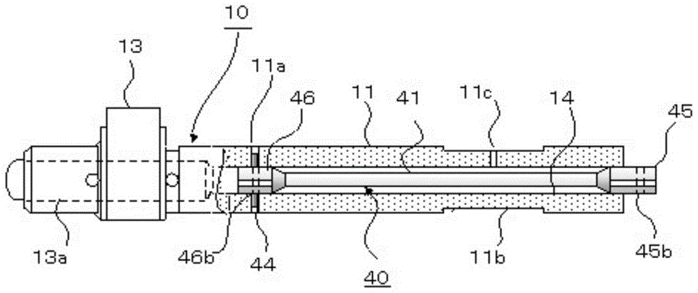
[0059] The characteristic of this embodiment is that the torsion bar spring 40 is equipped in the shaft center hole 14 provided in the main shaft 11 of the eccentric shaft 10, and the C action end 46 and the R action end 45 equipped at both ends are respectively connected to the eccentric shaft 10 and the rotor. 30, and the rotor 30 provided with the main...

Embodiment 2

[0088] The maximum value of the phase angle θ3 fluctuates greatly due to different operating conditions. In the case of a rotary compressor installed in an air conditioner, generally, θ3 becomes larger in proportion to the difference between the high-pressure side pressure and the low-pressure side pressure. Generally speaking, during cooling operation, θ3 will increase during the day when the air conditioning load is high, and will decrease at night when the air conditioning load is low. However, the reverse is true during heating operation. In addition, in the model equipped with an inverter motor with variable rotation speed, not only the air conditioning load, but also the inertial mass of the rotor is considered.

[0089] As mentioned above, if θ3 is too large during fluctuations in conditions such as operating load, the synchronous speed of the stator and rotor cannot be maintained, that is, a step-out phenomenon may occur, and the motor may stop suddenly. The present ...

Embodiment 3

[0101] Embodiment 1 is a manufacturing method in which the compression mechanism 5 and the rotor 30 are integrated and fixed in the inner diameter of the casing. In contrast to this method, after fixing the compression mechanism 5 and the stator 4 to the inner diameter of the housing 2, the method of inserting the rotor 30 into the main shaft 11 and assembling is also popularized. This embodiment corresponds to the latter method.

[0102] exist Figure 12 and Figure 13 In the center of the R action end 45 and the round pipe end 36, there is a rod groove 45c ( Figure 13 ) and round pipe groove 36c. After the rotor 30 is inserted into the main shaft 11, the two grooves are made in the same direction, and the R moment bars 43 are inserted into these grooves. Thereafter, the flat washer 47 is inserted into the outer periphery of the R-action end 45, and the C-stop ring 48 is inserted into the circumferential groove provided in the R-action end 45, so that the rotor 30 is fix...


PUM


Abstract

The invention discloses a rotary compressor and a refrigeration cycle device. The rotary compressor comprises a motor with a stator and a rotor, a compressing mechanism and a torsion rod spring, wherein the compressing mechanism comprises an eccentric shaft, the eccentric shaft and the rotor can rotate and slide relative to each other, and the eccentric shaft is provided with a shaft middle hole which serves as an opening of a shaft section; the compressing mechanism is provided with a compressing cavity, the compressing cavity is internally provided with a compressing component driven by the eccentric shaft, and motion ends on two sides of the torsion rod spring are respectively connected with the rotor and the shaft middle hole. In the motion of the compressing component, the difference between the rotary angle of the eccentric shaft and the rotary angle of the rotor is a phase angle, and the phase angle can be increased and decreased. According to the rotary compressor, the angular speed is stable due to the torque buffering effect of the rotor, and the problem that the efficiency of the motor is reduced is not generated.

Description

technical field [0001] The invention relates to the refrigeration field, in particular to a rotary compressor and a refrigeration cycle device. Background technique [0002] In order to reduce the rotary vibration of the rotary compressor, the motor torque control technology related to the waveform synthesis of the DC inverter motor was proposed around 1990, and the application of this method has been progressing since then. The motor torque control technology is to detect the change of the shaft torque while detecting the rotation position of the rotor, and synthesize the motor torque waveform to make the motor torque approximate to the eccentric shaft torque (hereinafter referred to as the shaft torque) and stabilize the angular velocity of the rotating rotor. However, the disadvantage of waveform synthesis is that the efficiency of the motor will decrease, so it is mostly used in a limited range such as low speed. Contents of the invention [0003] The present inventio...

Claims


Application Information

Patent Timeline
Patent Type & Authority Patents(China)
IPC IPC(8): F04C23/02F04C29/00
CPCF04C23/02F04C29/00
Inventor 小津政雄喻继江张诚郭宏周杏标钟亮闫丽丽王玲
Owner GUANGDONG MEIZHI COMPRESSOR
Why Eureka
Try Eureka