Separate flow path type of gas-air mixing device

A mixing device and gas technology, applied in the direction of gas and gas/steam mixing, burners, combustion methods, etc., can solve the problems of up and down vibration of the separation membrane, increase of gas supply pressure, unstable operation, etc., to minimize flow loss, Effect of reducing flow noise and simplifying the flow path

Active Publication Date: 2013-09-25
KYUNGDONG NAVIEN
View PDF7 Cites 9 Cited by
  • Summary
  • Abstract
  • Description
  • Claims
  • Application Information

AI Technical Summary

Problems solved by technology

Therefore, in order to make the regulation ratio (TDR) 3:1, the differential pressure ratio needs to be 9:1, and in order to make the regulation ratio (TDR) 10:1, the differential pressure ratio needs to be 100:1. Problem: It is impossible to increase the gas supply pressure infinitely
[0022] In addition, since the temperature of the excess air is raised to the temperature of the exhaust gas, a part of the heat generated by fuel combustion is used to increase the temperature of the excess air, so that heat loss occurs
[0023] Therefore, when the figure 2 When the combustion device shown above is applied to a condensing boiler, there is a problem that it is difficult to expect high efficiency in a low output power range (that is, when combustion is performed only in the 1-stage region or 2-stage region).
However, in the above-mentioned manner, the other end falls in free fall due to its own weight, and when a negative pressure is applied by a blower, air flows in according to the pressure difference, and the separation membrane A is lifted up due to the speed of the inflowing air; The following problems: When the amount of air changes, the separation membrane vibrates up and down, and the operation is unstable
In addition, when dust or foreign matter etc. accumulate on the hinge, there is a problem of not running smoothly

Method used


Image

  • Separate flow path type of gas-air mixing device
  • Separate flow path type of gas-air mixing device
  • Separate flow path type of gas-air mixing device

Examples


Embodiment Construction

[0054] Preferred embodiments of the present invention will be described in more detail with reference to the following drawings. In the drawings, similar or identical technical features are indicated by similar or identical reference signs.

[0055] refer to Figure 5 and Image 6 , an exemplary embodiment of a channel-separated gas-air mixing device according to an embodiment of the present invention will be described.

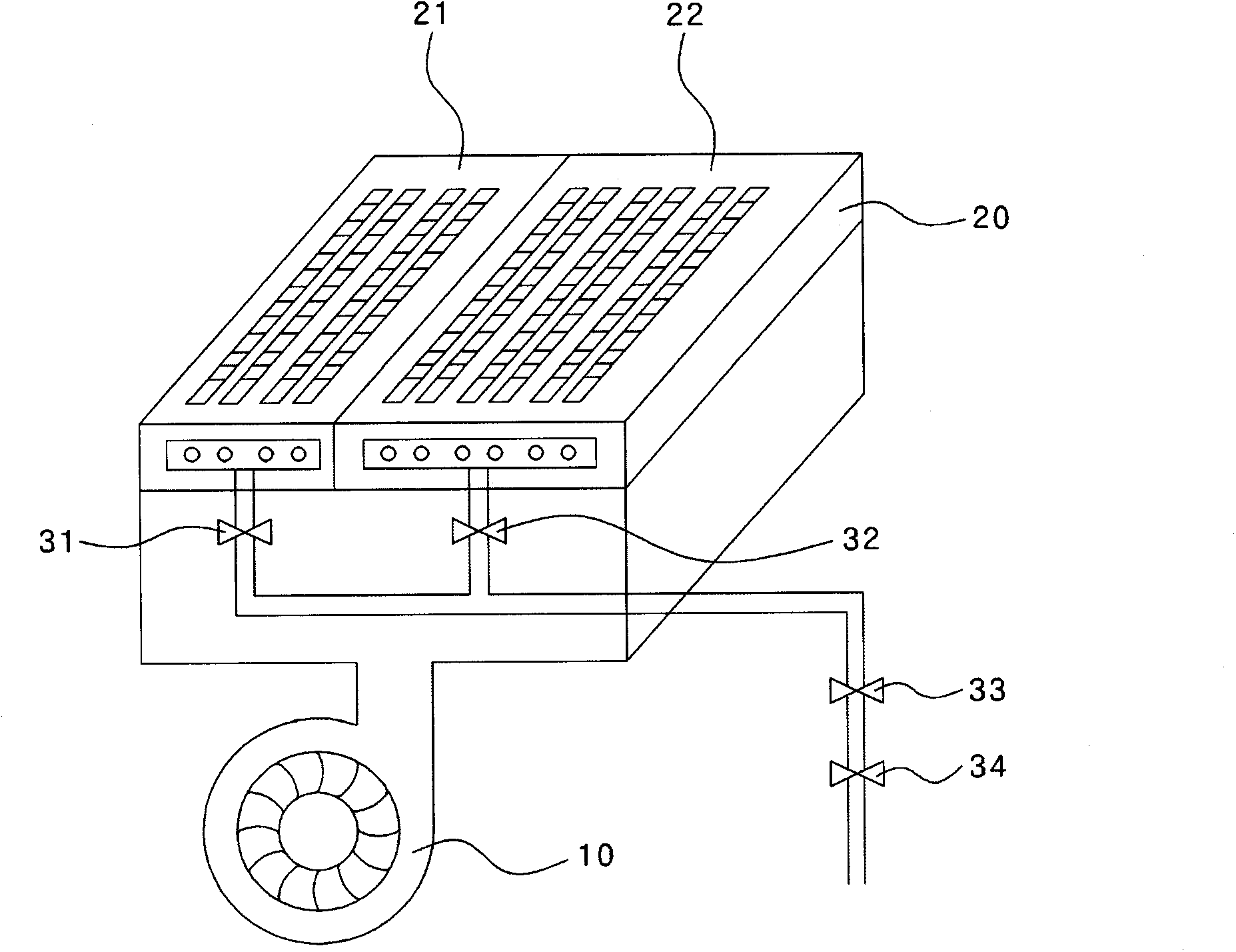
[0056] As far as the flow path separation type gas-air mixing device of the present invention is concerned, the gas supply pipe 112 of the fuel gas is branched into a plurality of gas flow paths, for example, two gas flow paths 115, 16 are branched; the air supply pipe 113 is branched into The plurality of air flow paths are, for example, branched into two air flow paths 117 and 118 .

[0057] Image 6 Schematically shows the state of the flow path separation type gas-air mixing device of the present invention in the high output power mode. refer to Im...


PUM


Abstract

According to the present invention, a gas-air mixing device used in a gas boiler comprises: a gas supply tube branched into a first gas flow path and a second gas flow path; an air supply tube branched into a first air flow path and a second air flow path by means of an air-flow-path branching apparatus; a pressure valve which is connected to the inlet port side of the gas supply tube in order to adjust the supply rate of gas being supplied to the gas supply tube; and a drive unit in which two valve bodies are connected to a rod that moves vertically up and down due to the magnetic force of an electromagnet; and the air-flow-path branching apparatus is formed so as to have a slot that can link through to either the first air flow path or the second air flow path, and so as to have a joining part which the rod can pass through in a position corresponding to the slot.

Description

technical field [0001] The present invention relates to a gas-air mixing device of a gas boiler, more specifically, to a flow path separation type gas-air mixing device for improving the regulation ratio. Background technique [0002] Generally, various types of boilers for heating are developed and used according to the required area or installation purpose, and there are gasoline boilers, gas boilers, and electric boilers depending on the fuel supplied. [0003] In such boilers, especially gas-fired boilers, as a method of burning gas fuel, in the case of premix burners, the combustion method is as follows: pre-mixing gas and air in a mixing ratio that is optimal for combustion After that, the mixed gas (air+gas) is supplied to the surface of the flame hole and combusted. [0004] In addition, the turn-down ratio (Turn-Down Ratio; TDR) is set in the gas boiler. The so-called turn-down ratio (TDR) refers to the difference between the maximum gas consumption and the minimum...

Claims


Application Information

Patent Timeline
Patent Type & Authority Applications(China)
IPC IPC(8): F23D14/22F23D14/62B01F23/10
CPCF23N1/02F23D14/62F23D14/36F23D14/60F23N1/005F23D14/02F23N2235/18F23N2233/08F23N2235/06F23D14/22B01F23/191
Inventor 孙承吉
Owner KYUNGDONG NAVIEN
Why Eureka
Try Eureka