Energy-saving type grain drying storehouse

A grain drying warehouse, energy-saving technology, applied in the direction of static material dryer, drying solid material, drying gas arrangement, etc., can solve the problems of poor drying uniformity, limited efficiency, difficult hot air in the central area, etc., and achieve low energy waste The effect of chemicalization and energy waste is the most

Inactive Publication Date: 2015-07-01
池润霖
View PDF6 Cites 4 Cited by
  • Summary
  • Abstract
  • Description
  • Claims
  • Application Information

AI Technical Summary

Problems solved by technology

For large farmers or agricultural management units, not only do not have a wide enough field, but also do not have so much energy to spread and turn the grain; for this reason, for large-scale grain storage, grain dryers with drying functions are usually used. warehouse
However, although the current dry barns have many structural forms, they all use hot air to dry the grains piled up in the barn as a whole. After the grains on the outer periphery of the grain heap are dried, the internal moisture is sucked to the outside, and then dried by the hot air; The air still has a relatively high temperature, and the heat is directly discharged to the outside, which further causes waste of heat
It can be seen that the current dry barn has poor drying uniformity and very limited efficiency, which will lead to a lot of waste of heat energy

Method used


Image

  • Energy-saving type grain drying storehouse
  • Energy-saving type grain drying storehouse
  • Energy-saving type grain drying storehouse

Examples


Embodiment Construction

[0012] Below in conjunction with accompanying drawing and embodiment the present invention is further described:

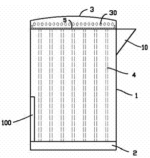
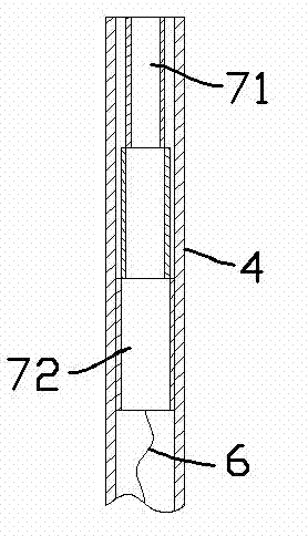
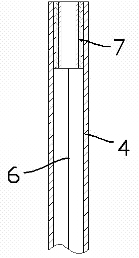
[0013] Such as figure 1 As shown, the energy-saving grain drying bin includes a bin body 1, a base 2 is provided below the bin body 1, a bin cover 3 is covered above the bin body 1, and a feed inlet 10 is provided on the upper side of the bin body 1; In the cross-section surrounded by the warehouse body 1, there are evenly distributed vertically extending heat pipes 4, and the peripheral walls of the heat pipes 4 are evenly distributed with pores that can block grains, that is, the surrounding walls of the heat pipes are ventilated, but it is not allowed The grains enter the heat pipe; the heat pipe 4 is provided with a heating device; one end of the heat pipe 4 extends to the base 2 and communicates with the outside world, and the other end extends to the warehouse body 1 and the warehouse cover 3 The surface of the net plate at the joint; the periphery of the n...


PUM


Abstract

The invention provides an energy-saving type grain drying storehouse. The energy-saving type grain drying storehouse comprises a storehouse body. A base is arranged under the storehouse body, the top of the storehouse body is covered by a storehouse cover, and a feeding inlet is formed in the upper side of the storehouse body. The cross section covered by the storehouse body is evenly provided with heat conducting pipes which extend vertically, and the circumferential wall of each heat conducting pipe is evenly provided with pores capable of blocking grain. A heating device is arranged inside each heat conducting pipe. One ends of the heat conducting pipes extend to the base, and are communicated with the outside, and the other ends of the heat conducting pipes extend to the surface of a net board which is transversely arranged on the connecting portion of the storehouse body and the storehouse cover. The periphery of the net board flanges upward to form a tablet-shaped container. The tablet container is filled with drying agents. Venting holes are formed in the circumferential wall of the storehouse cover. According to the energy-saving type grain drying storehouse, drying can be evenly carried out on the grain, the drying efficiency is high, and the heat waste is little.

Description

technical field [0001] The invention relates to the field of agricultural technical equipment, in particular to an energy-saving grain drying bin. Background technique [0002] In the field of agriculture, harvested food usually needs to be stored for long-term use; especially for grains, grains need to be stored in barns. Because grains are stored for a long time, if the grains are wet, mildew will occur, resulting in a large number of bacteria in the grains, which will seriously affect the quality and storage period of the grains. [0003] In this regard, for ordinary farmers, the grain can still be spread out on the field regularly for tumbling. For large farmers or agricultural management units, not only do not have a wide enough field, but also do not have so much energy to spread and turn the grain; for this reason, for large-scale grain storage, grain dryers with drying functions are usually used. warehouse. However, although the current dry barns have many struc...

Claims


Application Information

Patent Timeline
Patent Type & Authority Applications(China)
IPC IPC(8): F26B9/02F26B21/00F26B23/06F26B25/00
Inventor 朱虹斐
Owner 池润霖
Why Eureka
Try Eureka