
Optical axis orientation consistency detection system and method of corner reflector or corner reflector array

A corner reflector and optical axis pointing technology, applied in the field of optical testing, can solve problems such as no public reports, inconsistent brightness and size of corner reflector arrays, and no special device or method for testing optical axis consistency

Inactive Publication Date: 2015-07-01
XI'AN INST OF OPTICS & FINE MECHANICS - CHINESE ACAD OF SCI
View PDF10 Cites 7 Cited by
  • Summary
  • Abstract
  • Description
  • Claims
  • Application Information

AI Technical Summary

Problems solved by technology

[0005] In actual use, the strength of the light energy returned by the corner reflector directly affects the positioning accuracy of the device, especially when the corner reflector array is used as the target source, due to the inconsistency of the pointing of each sub-corner reflector in the corner reflector array , it will inevitably lead to inconsistency in the brightness and size of the corner reflector array captured in the field of view of the observation and positioning camera, which will affect the interpretation accuracy of the angle reflector carrier attitude of the observation and positioning camera
[0006] With the development of aerospace technology, higher requirements are put forward for the optical axis consistency of the corner reflectors and the sub-corner reflectors in the corner reflector array. There is no relevant public report on the device or method for the optical axis consistency of the sub-corner reflector

Method used


Image

  • Optical axis orientation consistency detection system and method of corner reflector or corner reflector array
  • Optical axis orientation consistency detection system and method of corner reflector or corner reflector array
  • Optical axis orientation consistency detection system and method of corner reflector or corner reflector array

Examples


Embodiment Construction

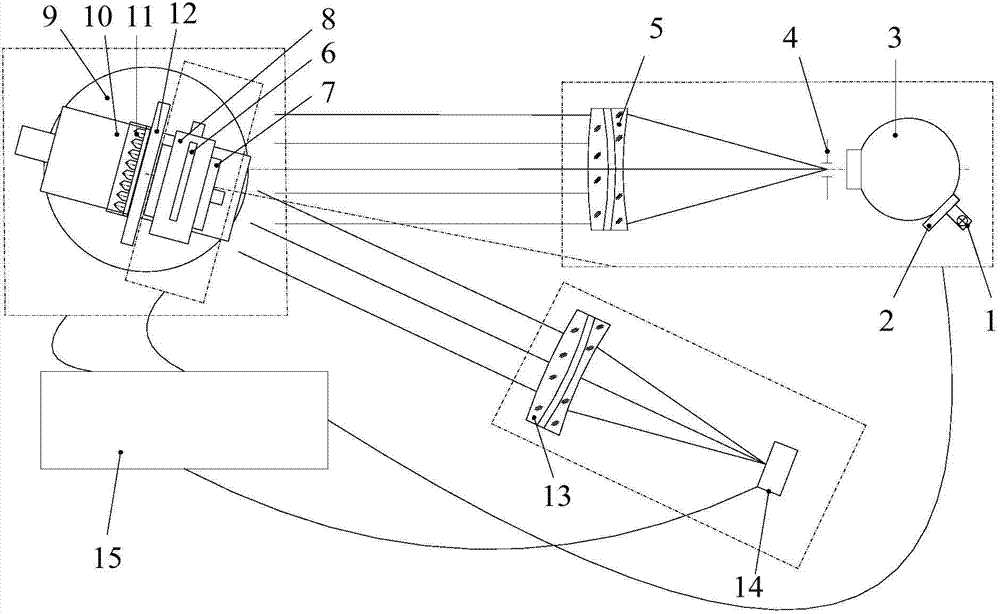
[0045] see figure 1 , the present invention provides a corner reflector or a corner reflector array optical axis pointing consistency detection system (abbreviation: detection system), which includes a collimated light source unit, a liquid crystal light valve dynamic diaphragm unit, and a corner reflector attitude adjustment unit , CCD measurement unit and control unit 15; the liquid crystal light valve dynamic diaphragm unit is arranged on the outgoing light path of the collimated light source unit; the corner reflector attitude adjustment unit is arranged on the outgoing light path of the liquid crystal light valve dynamic diaphragm unit; the measured angle The reflector or corner reflector array 11 is arranged on the corner reflector attitude adjustment unit; the CCD measurement unit is arranged on the optical path where the reflected light reflected by the measured corner reflector or corner reflector array is located; the control unit 15 is respectively connected with the...


PUM


Abstract

The invention discloses an optical axis orientation consistency detection system and method of a corner reflector or a corner reflector array. The optical axis orientation consistency detection system includes a collimated light source unit, an LCLV (liquid crystal light valve) dynamic aperture unit, a corner reflector attitude adjustment unit, a CCD (charge coupled device) measurement unit and a control unit. The LCLV dynamic aperture unit is arranged on an emergent light path of the collimated light source unit. The corner reflector attitude adjustment unit is arranged on an emergent light path of the LCLV dynamic aperture unit. The corner reflector or corner reflector array to be measured is arranged on the corner reflector attitude adjustment unit. The CCD measurement unit is arranged on a light path in which the reflected light, reflected by the corner reflector or corner reflector array to be measured, exists. The control unit is respectively connected with the collimated light source unit, the LCLV dynamic aperture unit, the corner reflector attitude adjustment unit and the CCD measurement unit. By the use of the optical axis orientation consistency detection system and method, quickly and accurately measured is an included angles between a corner reflector mounting datum plane and the optical axis orientation of the corner reflector or the sub-corner reflectors of the corner reflector array.

Description

technical field [0001] The invention belongs to the technical field of optical testing, and relates to a detection system and a detection method for the consistency of the direction of the optical axis of a corner reflector or the consistency of the direction of the optical axis of each sub-corner reflector in a corner reflector array. Background technique [0002] The corner reflector is an optical device that makes the light incident into the corner reflector return in a direction parallel to the incident direction, and is widely used in laser ranging systems such as artificial satellites and aircraft. The corner reflector makes the laser emitted by the laser return to the laser rangefinder system in the direction opposite to the incident direction, and the distance between the target and the laser rangefinder can be calculated by measuring the time when the laser rangefinder emits the laser and receives the returned laser. distance. [0003] With the development of aeros...

Claims


Application Information

Patent Timeline
IPC IPC(8): G01M11/02
Inventor 刘峰周艳赵建科徐亮陈永权郭毅胡丹丹张洁王争锋
Owner XI'AN INST OF OPTICS & FINE MECHANICS - CHINESE ACAD OF SCI
Learn More