
Method and system for fire detection, warning, positioning and extinguishing

A fire detection and detection area technology, which is applied in fire alarms, fire alarms that rely on radiation effects, and alarms, etc., can solve the problem that it is difficult to adapt to the detection needs of outdoor scenes, cannot be directly applied to fire detection, and the temperature measurement type is expensive. problems, to achieve the effect of avoiding the interference of ambient light, high accuracy, and strong anti-interference ability

Active Publication Date: 2015-07-01
DALIAN SHIELD SAFE TECH LTD
View PDF6 Cites 28 Cited by
  • Summary
  • Abstract
  • Description
  • Claims
  • Application Information

AI Technical Summary

Problems solved by technology

Infrared thermal imaging cameras are divided into two types: temperature measurement type and non-temperature measurement type. Among them, the temperature measurement type is more expensive, and needs to accurately input parameters such as the emissivity, distance, and ambient temperature of the object to be measured, and it is difficult to adapt to complex outdoor scene detection. Requirements; non-temperature-measuring thermal imagers can only output the difference in thermal radiation in the scene, and automatically map to 256-level grayscale or color output. When there are many thermal radiators in the environment, they cannot be distinguished, and there is a lot of interference, so they cannot be directly applied fire detection

Method used


Image

  • Method and system for fire detection, warning, positioning and extinguishing
  • Method and system for fire detection, warning, positioning and extinguishing
  • Method and system for fire detection, warning, positioning and extinguishing

Examples


Embodiment Construction

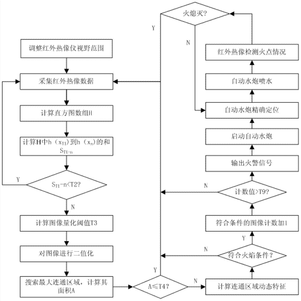
[0016] The present invention will be described in detail below in conjunction with the accompanying drawings. However, it should be understood that the accompanying drawings are provided only for better understanding of the present invention, and they should not be construed as limiting the present invention. In the description of the present invention, it should be understood that the terms "first", "second" and so on are only used for the purpose of description, and should not be understood as indicating or implying relative importance.

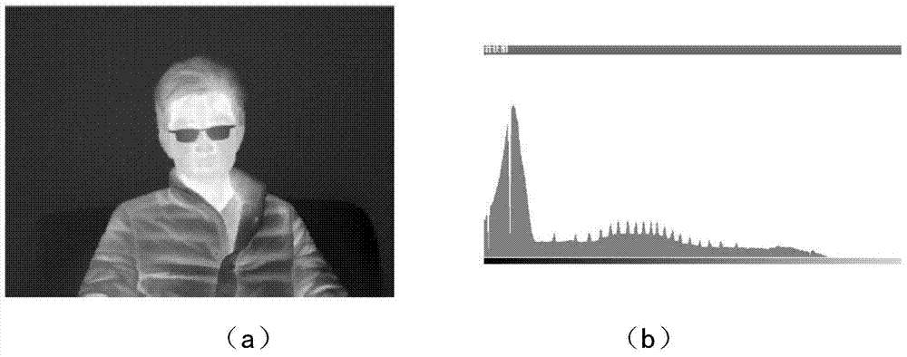
[0017] The infrared thermal imaging system based on the uncooled focal plane infrared detector has high image resolution and low price, and can present ideal thermal contrast; the direct output of the uncooled focal plane infrared detector is 12 to 14 By directly processing the original signal, the thermal radiation signal can be reasonably quantified, thereby removing interference and effectively extracting fire point information.

[0018...


PUM


Abstract

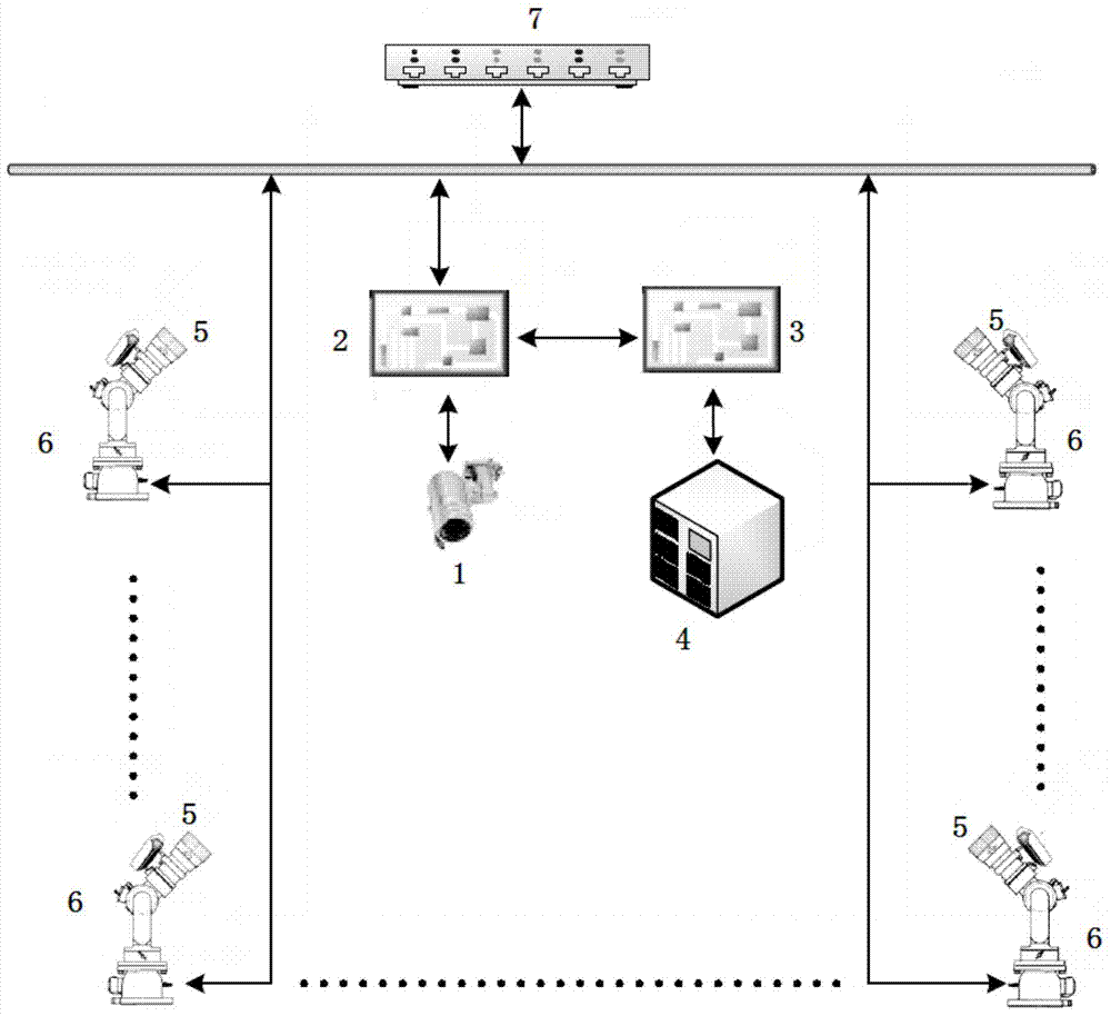
The invention relates to a method and a system for fire detection, warning, positioning and extinguishing. The system comprises a thermal infrared imager, an image processing system, a warning output system, a warning master, double-band image detectors, automatic fire monitors and a network switch. Each dual-band image detector is connected with one automatic fire monitor through a RS485 interface, forming an automatic linked fire monitor. The thermal infrared imager is connected to the input end of the image processing system through a data line; the first output end of the image processing system is connected to the input end of the warning output system through an RS232 interface; the output end of the warning output system is connected to the warning master through an RS485 bus; the second output end of the image processing system is connected with the network switch through an RJ45 interface; the automatic fire monitors are parallelly connected with the network switch through an RJ45 interface, so that the image processing system and the automatic linked fire monitors form a local network; the network switch is networked with a peripheral fire monitoring network through an RJ45 interface. The method and the system are widely applicable to the fields, such as large-scale petrochemical factories, large-scale outdoor ports and large-scale outdoor public places.

Description

technical field [0001] The invention relates to the technical field of fire monitoring and automatic fire extinguishing, in particular to a fire detection, alarm, positioning and extinguishing method and system suitable for automatic large outdoor spaces. Background technique [0002] Fire is one of the main disasters that most frequently and commonly threatens public safety and social development. Fire alarm, positioning and extinguishing systems are important equipment related to people's lives and property safety. At present, the fire water monitor is an important fire-fighting equipment for long-distance fire fighting. It usually cooperates with various fire detection equipment to form a large-space fire-extinguishing system. At present, outdoor fire-fighting water monitors are mainly manual-controlled, with poor positioning accuracy and long extinguishing time, posing major safety hazards. With the development of technology, the application of automatic fire water cann...

Claims


Application Information

Patent Timeline
Patent Type & Authority Applications(China)
IPC IPC(8): G08B17/12A62C31/00A62C37/00
CPCA62C31/00A62C37/00G08B17/125
Inventor 胡英李爱国张旭汪洋
Owner DALIAN SHIELD SAFE TECH LTD
Learn More