
Electric fuse structure

A technology of electric fuses and fuses, applied in circuits, electrical components, electric solid devices, etc., can solve the inconvenience of circuit designers and the inability to obtain constant resistance value changes, etc., and achieve the effect of flexible circuit design

Active Publication Date: 2017-09-22
SEMICON MFG INT (SHANGHAI) CORP
View PDF8 Cites 0 Cited by
  • Summary
  • Abstract
  • Description
  • Claims
  • Application Information

AI Technical Summary

Problems solved by technology

[0006] The problem to be solved by the present invention is: the existing electric fuse structure cannot obtain a constant resistance value change before and after fusing, which brings inconvenience to the circuit designer and brings certain limitations to the circuit design

Method used


Image

  • Electric fuse structure
  • Electric fuse structure
  • Electric fuse structure

Examples


Embodiment Construction

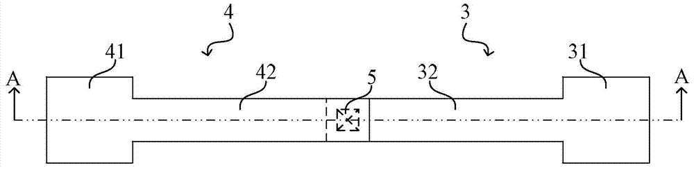
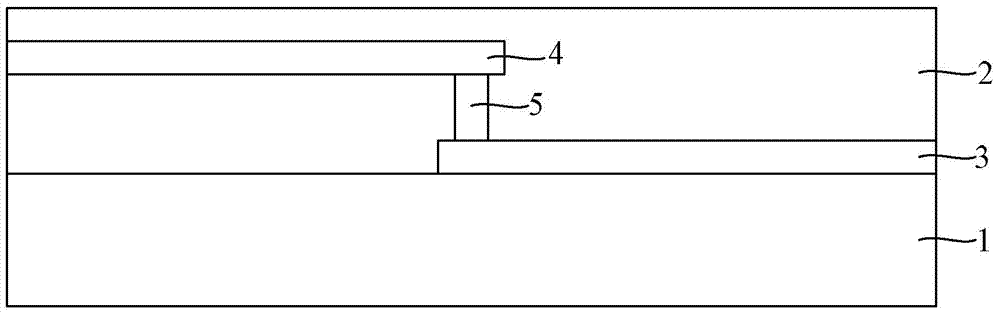
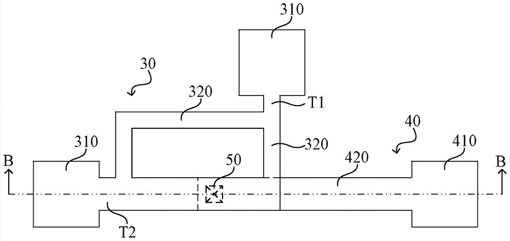
[0038] It can be seen from the foregoing that the existing electric fuse structure has only two electrodes, namely an anode and a cathode, and the two electrodes are electrically connected through a conductive plug. According to the fusing mechanism of the electric fuse structure, when the electric fuse structure is blown, the position of the conductive plug will be blown, so that a constant resistance value cannot be measured at the two electrodes after the electric fuse structure is blown.

[0039] In view of this, the present invention proposes an improved electric fuse structure, by arranging a first electric fuse unit including a plurality of first fuses in the first conductive pattern layer of the electric fuse structure, and at least one first A first fuse of an electric fuse unit is electrically connected with the conductive plug, so that when the electric fuse structure is blown, although the position of the conductive plug will be blown, so that after the electric fus...


PUM


Abstract

An electric fuse structure, comprising: a substrate; a dielectric layer on the substrate; a first conductive pattern layer in the dielectric layer, a second conductive pattern layer, and a first conductive pattern layer and a second conductive pattern layer Conductive plugs between them, wherein: the first conductive pattern layer includes: at least one first electric fuse unit, and the first electric fuse unit includes: two first electrodes, and multiple electrodes located between the two first electrodes a first fuse, the first end and the second end of the first fuse are respectively connected to two first electrodes; the second conductive pattern layer includes: a second electrode, and a second fuse connected to the second electrode The wire; the conductive plug is electrically connected to the second fuse and a first fuse contact of the at least one first electric fuse unit. It solves the problem that the existing electric fuse structure cannot obtain a constant resistance value change before and after fusing, which brings inconvenience to circuit designers and brings certain limitations to circuit design.

Description

technical field [0001] The invention relates to the technical field of semiconductors, in particular to an electric fuse structure. Background technique [0002] As feature sizes continue to decrease, semiconductor devices are increasingly susceptible to impurities or defects in the silicon substrate, and the failure of a single diode or MOS transistor often leads to the failure of the entire integrated circuit chip. In order to solve the above problems and improve the yield, some redundant circuits are often formed in the integrated circuit chip. When it is found that some devices cannot work normally after the completion of the manufacturing process, the failed circuit can be electrically isolated from other circuit modules through the fusing of the electric fuse structure, and the original failed circuit can be replaced with a redundant circuit. Especially in the manufacturing process of memory, due to the large number of memory cells, it is inevitable that some memory c...

Claims


Application Information

Patent Timeline
Patent Type & Authority Patents(China)
IPC IPC(8): H01L23/525
Inventor 廖淼
Owner SEMICON MFG INT (SHANGHAI) CORP
Learn More