Combined type brushless direct-current permanent magnet magnetic flow switching motor and axial proportion calculation method

A magnetic flux switching motor, combined technology, applied in electrical components, electromechanical devices, etc., can solve the problems of narrow speed range, poor field weakening ability of brushless DC motors, etc., achieves low risk of demagnetization, easy speed sensorless technology, Control simple effects

Active Publication Date: 2015-07-01
NANJING UNIV OF AERONAUTICS & ASTRONAUTICS
View PDF6 Cites 11 Cited by
  • Summary
  • Abstract
  • Description
  • Claims
  • Application Information

AI Technical Summary

Problems solved by technology

[0012] The technical problem to be solved by the present invention is to provide a combined brushless DC permanent magnet flux switching m

Method used


Image

  • Combined type brushless direct-current permanent magnet magnetic flow switching motor and axial proportion calculation method
  • Combined type brushless direct-current permanent magnet magnetic flow switching motor and axial proportion calculation method
  • Combined type brushless direct-current permanent magnet magnetic flow switching motor and axial proportion calculation method

Examples


Embodiment 1

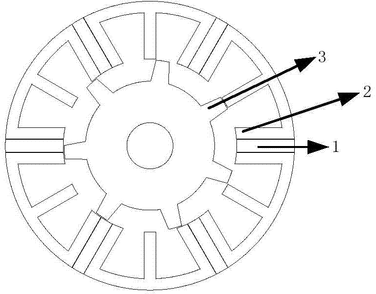
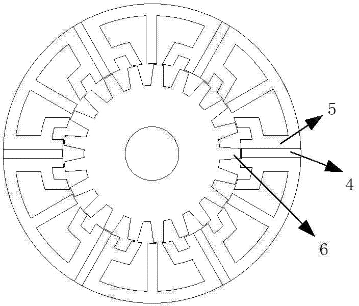
[0041] In the first embodiment, the stator core of the first motor and the stator core of the second motor are both 6-tooth structures, the number of teeth of the first rotor is 7, and the number of teeth of the second rotor is 21 as an example to further illustrate the technical solution of the present invention:

[0042] The excitation direction of the excitation source on the stator teeth of the stator of the first motor and the stator of the second motor can be the same or opposite. The first motor and the second motor are separated by a magnetic isolation material; The first rotor teeth of the second motor rotor are staggered by a rotor offset angle, the offset angle is An integer multiple of.

[0043] In the combined brushless DC permanent magnetic flux switching motor, if the stator of the first motor and the stator of the second motor have the same stator teeth, the excitation direction of the excitation source is the same, then the first rotor tooth of the first motor roto...

Embodiment 2

[0069] The second embodiment is a 6 / 5C iron core permanent magnetic flux switching motor and a 6 / 15 multi-tooth fault-tolerant permanent magnetic flux switching motor. Among them, 6 / 5C iron core permanent magnetic flux switching motors such as Figure 7 As shown, the 6 / 15 multi-tooth fault-tolerant permanent magnetic flux switching motor is as Figure 8 Shown. Figure 7 with Figure 8

Embodiment 3

[0070] The third embodiment is a 6 / 8C iron core permanent magnetic flux switching motor and a 6 / 24 multi-tooth fault-tolerant permanent magnetic flux switching motor. Among them, the 6 / 8C iron core permanent magnetic flux switching motor such as Picture 9 As shown, the 6 / 24 multi-tooth fault-tolerant permanent magnetic flux switching motor is as Picture 10 Shown.


PUM


Abstract

The invention discloses a combined type brushless direct-current permanent magnet magnetic flow switching motor. The combined type brushless direct-current permanent magnet magnetic flow switching motor comprises a first motor and a second motor, wherein each of the first motor and the second motor comprises a stator and a rotor; stator teeth of the first motor and stator teeth of the second motor are arranged in pairs one by one; the excitation directions of two stator excitation sources on each pair of the stator teeth are the same or opposite; each pair of the stator teeth share one stator winding; the tooth quantity of the rotor of the second motor is three times as much as that of the tooth quantity of the rotor of the first motor; a deviation angle is formed between a first rotor tooth of the first motor and a first rotor tooth of the second motor. According to the combined type brushless direct-current permanent magnet magnetic flow switching motor, the weak magnetic inductance value of the motors is increased and the weak magnetic current is reduced; the constant power region operation capability of the motors is improved. With the adoption of a combined mode and an axial length determination method, the motor has no-load square wave counter potential, large weak magnetic inductance and a wide rotary speed operation range, and is suitable for a brushless direct-current operation mode and can realize a speed sensorless technology in a full-speed variable load range.

Description

Technical field [0001] The invention belongs to the field of permanent magnet motors, and specifically relates to a combined brushless DC permanent magnet flux switching motor and an axial ratio calculation method thereof. Background technique [0002] Permanent magnet motors have the advantages of high efficiency, high torque density, and high power density, and are widely used in defense, transportation, transportation, new energy and other fields. [0003] According to the location of permanent magnets, permanent magnet motors are generally divided into rotor permanent magnet motors and stator permanent magnet motors. Three classic stator permanent magnet motors are flux-reversing permanent magnet motors, doubly salient permanent magnet motors, and flux-switching permanent magnet motors. Among them, the armature magnetic field of the flux-reversing permanent magnet motor is in series with the permanent magnet field. , Permanent magnets have the risk of demagnetization. In the ...

Claims


Application Information

Patent Timeline
IPC IPC(8): H02K16/00
CPCH02K16/00
Inventor 王宇邓智泉
Owner NANJING UNIV OF AERONAUTICS & ASTRONAUTICS
Why Eureka
Try Eureka