
Current effective value minimizing control method for bidirectional half-bridge tri-level DC (Direct Current)-DC converter

A DC-DC, half-bridge three-level technology, applied in the direction of converting DC power input to DC power output, adjusting electrical variables, control/regulation systems, etc., can solve the problems of reducing converter efficiency, increasing circulating power and current stress, Issues such as increased switching device and magnetic component losses

Active Publication Date: 2015-07-01
成都拓及兴通科技有限公司
View PDF4 Cites 10 Cited by
  • Summary
  • Abstract
  • Description
  • Claims
  • Application Information

AI Technical Summary

Problems solved by technology

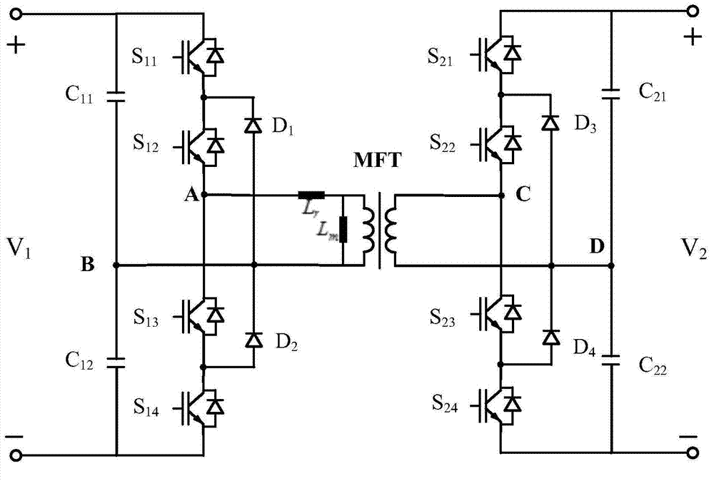
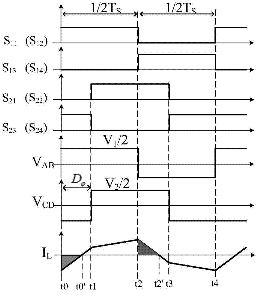
Phase shift control is simple and easy to implement, but it does not take advantage of figure 2 At the same time, because the inductor current lags behind the voltage, it also leads to power circulation in the input and output directions within a switching cycle (such as image 3 shaded part in
When the input and output voltage amplitudes do not match, the circulating power and current stress will increase greatly, thereby increasing the loss of switching devices and magnetic components, and reducing the efficiency of the converter

Method used


Image

  • Current effective value minimizing control method for bidirectional half-bridge tri-level DC (Direct Current)-DC converter
  • Current effective value minimizing control method for bidirectional half-bridge tri-level DC (Direct Current)-DC converter
  • Current effective value minimizing control method for bidirectional half-bridge tri-level DC (Direct Current)-DC converter

Examples


Embodiment Construction

[0055] According to the analysis steps of the control method provided in the Summary of the Invention part and the D that meets the control target provided by Table 1 1 、D 2 about the expression of Figure 5 When k=0.3, 0.5, 0.7, 0.9, D 1 、D 2 about control curve. The controller implements the specific implementation of the optimal control method proposed in this patent as Figure 7 Shown:

[0056] a) The voltage control module of the controller controls the load side voltage (V 2 ) and reference voltage (V 2ref ) error for feedback control, get shift phase

[0057] b), read in the result of a), and obtain the duty ratio D of the primary side bridge arm voltage according to Table 1 1 and the duty cycle of the secondary arm voltage D 2 :

[0058] when in the range of hour,

[0059] when in the range of hour,

[0060]

[0061] when in the range of when D 1 = 1, D 2 = 1;

[0062] c), the step a), b) obtained D. 1 and D 2 The input switch ...


PUM


Abstract

The invention discloses a current effective value minimizing control method for a bidirectional half-bridge tri-level DC (Direct Current)-DC converter. Three controlled quantities in a topological structure of the bidirectional half-bridge tri-level DC-DC converter are controllable, namely a primary side bridge arm middle point voltage duty ratio D1, a secondary side bridge middle point voltage duty ratio D2 and a phase shift angle Dalpha between primary side bridge arm middle point and secondary side bridge arm middle point voltage; minimized control of the current effective level is achieved under the premise that power required for transmission load is satisfied. According to the current effective value minimizing control method for a bidirectional half-bridge tri-level DC (Direct Current)-DC converter, D1, D2 and Dalpha is coordinately controlled, the current effective value of a transformer is minimum under the condition that the power required for the load is satisfied, copper loss of a magnetic element in a circuit and conduction losses of a switch tube are reduced, meanwhile switch tubes in the circuit can achieve zero-voltage conduction within the integral transmission power range, and switch loss of a power device is effectively reduced.

Description

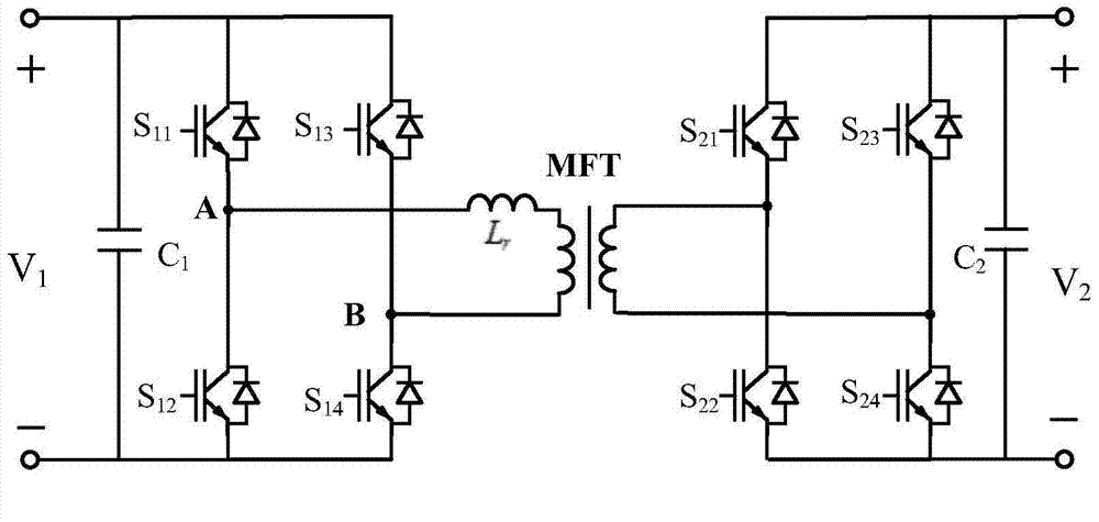
technical field [0001] The invention relates to a control method of an isolated bidirectional DC-DC converter, in particular to an optimal control of a bidirectional half-bridge three-level DC-DC converter. Background technique [0002] The isolated bidirectional DC-DC converter is a DC-DC converter that can operate in two quadrants and can realize electrical isolation on the input and output sides. As an important part of power electronic transformers, it is used in smart microgrids, distributed power generation systems and It is widely used in electric locomotive traction system. [0003] High-power isolated bidirectional DC-DC converters are more commonly used bidirectional full-bridge two-level circuit structure, and its topology is as follows figure 1 As shown, it consists of two symmetrical H-bridges, an intermediate frequency transformer and two DC stabilizing capacitors. The converter has a simple structure, high power density, electrical isolation and bi-direction...

Claims


Application Information

Patent Timeline
Patent Type & Authority Applications(China)
IPC IPC(8): H02M3/335
CPCH02M3/33576
Inventor 舒泽亮况祖杭郭潇潇何晓琼
Owner 成都拓及兴通科技有限公司
Learn More