
Method and device for starting and controlling switched reluctance motor

A switched reluctance motor, main drive technology, applied in motor control, electronic commutation motor control, single motor speed/torque control, etc., can solve problems such as instability, ramp resistance, electric vehicle jitter, etc. The effect of adding extra cost

Active Publication Date: 2018-05-22
NIDEC BEIJING DRIVE TECH CO LTD
View PDF3 Cites 0 Cited by
  • Summary
  • Abstract
  • Description
  • Claims
  • Application Information

AI Technical Summary

Problems solved by technology

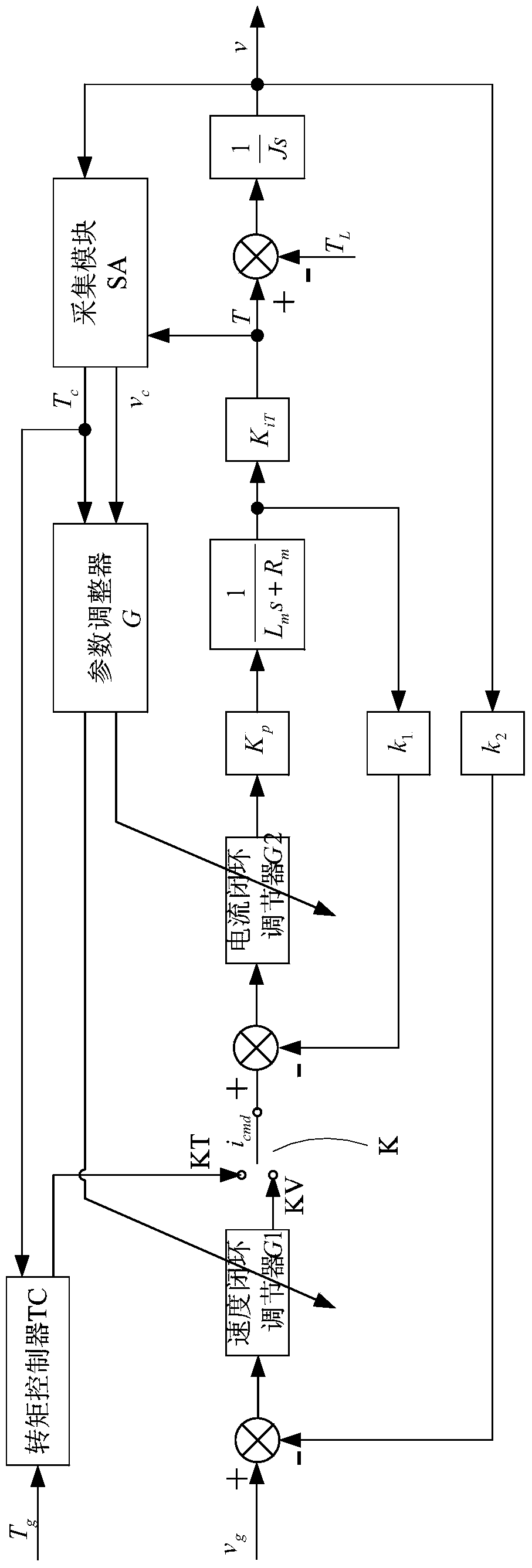
When starting on a slope, the gravity component of the electric vehicle along the direction of the slope will cause the resistance of the slope, which will cause the driving load of the switched reluctance motor to be different, that is, the moment of inertia J in the closed-loop block diagram is different, due to the current closed-loop and speed closed-loop The parameters of the PID regulator have been set, so the current closed-loop and speed closed-loop characteristics of the switched reluctance motor will change.
It is reflected in the driving performance of the vehicle. For example, the PID regulator parameters set according to the situation on the flat road are difficult to meet the requirement of fast output of large torque when starting on a slope, causing the electric vehicle to slip; The parameters of the PID regulator will make the current closed-loop and speed closed-loop overshoot of the switched reluctance motor large and unstable when starting on a flat road, which will cause the electric vehicle to vibrate and crash.
[0005] Existing electric vehicles use switched reluctance motors as the main drive motors, and it is difficult to take into account the different driving resistance conditions when starting on flat roads and starting on slopes, and the vehicle is prone to slipping, shaking and crashing

Method used


Image

  • Method and device for starting and controlling switched reluctance motor
  • Method and device for starting and controlling switched reluctance motor
  • Method and device for starting and controlling switched reluctance motor

Examples


Embodiment Construction

[0024] In order to further explain the technical means and effects of the present invention to achieve the intended purpose of the invention, the specific implementation of a switched reluctance motor start-up control method and device proposed according to the present invention will be described below in conjunction with the accompanying drawings and preferred embodiments. , structure, feature and effect thereof, detailed description is as follows. In the following description, different "one embodiment" or "embodiment" do not necessarily refer to the same embodiment. Furthermore, the particular features, structures, or characteristics of one or more embodiments may be combined in any suitable manner.

[0025] Embodiment of Switched Reluctance Motor Starting Control Method

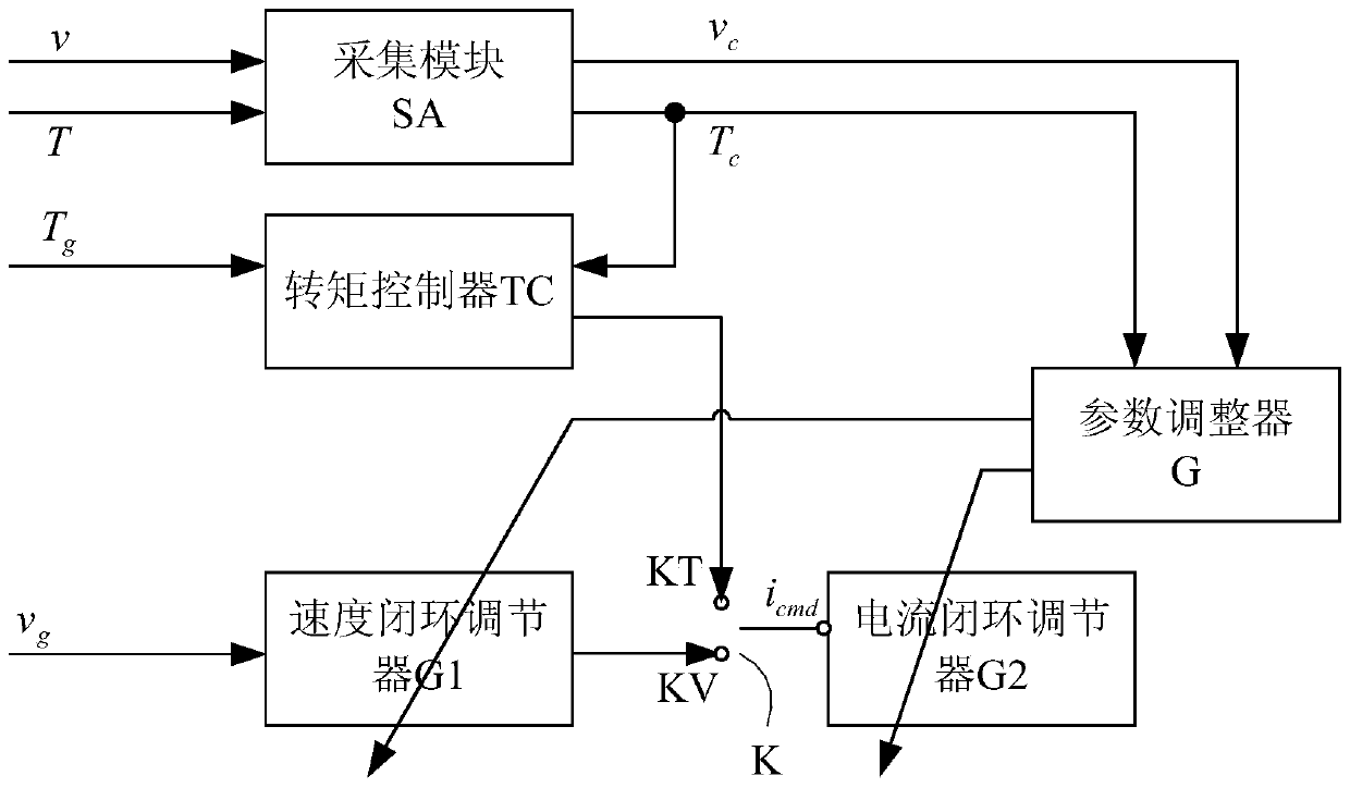
[0026] Such as figure 1 and figure 2 A switching reluctance motor startup control method shown includes: when starting, the switched reluctance motor is in the speed control mode; collecting the curre...


PUM


Abstract

The invention discloses a start control method and device for a switch reluctance motor. The method comprises the steps of acquiring the current torque signal and the current rotating speed signal outputted by the switch reluctance motor which is in a rotating speed control mode during starting; treating a PID regulator as a speed closed-loop regulator G1, wherein the parameters are K11, K12 and K13; adjusting the PID regulator as a current closed-loop regulator G2, wherein the parameters are K21, K22 and K23; treating one function / transfer function as a parameter adjusting module G; adjusting the parameters of the G1 and the G2 according to the current output torque T and the rotating speed v of the switch reluctance motor; expressing through a matrix equation which can be shown as [K11K12K13; K121K22K23]T=G([T v] T). The control method comprises an acquiring module SA, the speed closed-loop regulator G1, the current closed-loop regulator G2 and the parameter adjusting module G. With the adoption of the method and the device, the operation is smooth while starting on a flat road or starting on a slope, and slipping, jittering and colliding can be avoided.

Description

technical field [0001] The invention relates to the field of electric vehicle control, in particular to a starting control method and device for a switched reluctance motor. Background technique [0002] The switched reluctance motor is an excellent motor system for vehicles. Its own principle ensures that it has high reliability, high efficiency and wide speed regulation range. It is very suitable as the main drive motor of electric vehicles. [0003] The switched reluctance motor generally adopts a double closed-loop control structure, including a current closed loop and a speed closed loop. The current closed loop is the inner loop, and the speed closed loop is the outer loop. The current closed-loop and speed closed-loop of the switched reluctance motor generally use a PID regulator, which consists of three links: proportional, integral and differential, and the parameters of the three links need to be preset when used. The current closed-loop collects the winding curre...

Claims


Application Information

Patent Timeline
Patent Type & Authority Patents(China)
IPC IPC(8): H02P6/20
CPCH02P6/005H02P6/08H02P2207/05
Inventor 郭晓颖
Owner NIDEC BEIJING DRIVE TECH CO LTD
Learn More