Calibration method of camera optical axis detection apparatus

A technology of detection equipment and calibration method, which is applied in the field of calibration, can solve problems such as large investment, and achieve the effect of simple operation, cost saving, and accurate calibration

Active Publication Date: 2015-07-01
SUZHOU INVO AUTOMOTIVE ELECTRONICS
View PDF10 Cites 9 Cited by
  • Summary
  • Abstract
  • Description
  • Claims
  • Application Information

AI Technical Summary

Problems solved by technology

The intermediate process requires sophisticated equipment and high-standa

Method used


Image

  • Calibration method of camera optical axis detection apparatus
  • Calibration method of camera optical axis detection apparatus
  • Calibration method of camera optical axis detection apparatus

Examples


Example Embodiment

[0026] Example 1

[0027] 1. Place the camera on the optical axis detection device according to the test position, and take a screenshot of the picture mapped by the camera at this time.

[0028] 2. Open the picture with drawing software and read the center coordinate value (316, 245).

[0029] 3. Rotate the camera 180 degrees on the basis of the original test position, and take a screenshot of the picture mapped by the camera at this time.

[0030] 4. Open the picture with drawing software and read the center coordinates (326, 237).

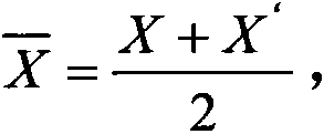
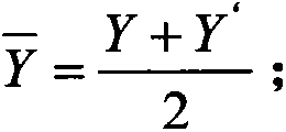
[0031] 5. Calculation: X ‾ = 316 + 326 2 = 321 , Y ‾ = 245 + 237 2 = 241 , The center value (321, 241) is obtained.

[0032] 6. Calculate the difference between the center value and the center coordinate value of the original position: ΔX=321-316=5, ΔY=241-245=-4.

[0033] 7. According to the difference obtained by the above calculation, move the equipment drawing 5 pixels to the right along the X ...

Example Embodiment

[0039] Example 2

[0040] 1. Place the camera on the optical axis detection device according to the test position, and take a screenshot of the picture mapped by the camera at this time.

[0041] 2. Open the picture with drawing software and read the center coordinate value (X, Y).

[0042] 3. Rotate the camera 180 degrees on the basis of the original test position, and take a screenshot of the image mapped by the camera at this time.

[0043] 4. Open the picture with drawing software and read the center coordinate value (X', Y').

[0044] 5. Do parallel experiments, that is, repeat steps 1 to 4 ten times, so as to avoid the occurrence of a single excessive error. The data obtained are shown in the following table.

[0045]

[0046] 6

[0047] Take the average of the horizontal and vertical coordinates as the data for subsequent calculations.

[0048] 6. Calculation: X ‾ = 316.373 + 321.439 2 = 318.906 ,

[0049] Y ‾ = 242.468 + 238.37...


PUM


Abstract

The invention discloses a calibration method of a camera optical axis detection apparatus. The calibration method is characterized by comprising the steps of placing the camera on the optical axis detection apparatus according to a test position, capturing a picture mapped by the camera at the moment, opening the picture by use of drawing software and reading central coordinate values (X, Y), rotating the camera by 180 degrees and reading the central coordinate values (X', Y'), calculating to obtain a center value as shown in the specification, calculating to obtain the difference (delta X, delta Y) between the center value and the central coordinate values of the original value, and moving an apparatus drawing according to (delta X, delta Y) along the X axis and the Y axis by the corresponding number of pixel points. The calibration method has the beneficial effect that the problem of center calibration of the high-precision camera detection apparatus is solved; compared with the prior art, the calibration method is simpler in operation and more accurate in calibration; according to the theory that the camera rotates by 180 degrees around the own center on the apparatus and the center does not change, the whole calibration process is completed in one step and strong digital judgment proof is provided; the cost of fabricating the standard camera is saved, the labor is saved and the production efficiency is improved.

Description

technical field [0001] The invention relates to a calibration method, in particular to a method for calibrating camera optical axis detection equipment. Background technique [0002] With the development of the times, the automobile industry has become an important part of the market economy. In developed countries, automobiles have basically become the means of transportation for most people. In developing countries, the demand for automobiles is also increasing day by day. The resulting car safety has become an important indicator for consumers to measure cars, and many car safety industries that have emerged have also launched fierce competition for this. As a part of car safety, the development of car cameras is like mushrooms after rain. [0003] The accuracy of the optical axis of a vehicle-mounted camera is a very important indicator for realizing the performance of a high-precision camera. At present, our determination of the optical axis is generally based on the de...

Claims


Application Information

Patent Timeline
IPC IPC(8): H04N17/00G06T7/00G06T7/80
Inventor 黄耀辉增田悟文旭易世春
Owner SUZHOU INVO AUTOMOTIVE ELECTRONICS
Why Eureka
Try Eureka