Membrane electrode device and fuel cell with such a membrane electrode device

A diaphragm electrode, fuel cell technology, applied in the direction of fuel cells, fuel cell parts, circuits, etc., can solve disadvantages and other problems

Active Publication Date: 2017-03-29
AUDI AG
View PDF7 Cites 0 Cited by
  • Summary
  • Abstract
  • Description
  • Claims
  • Application Information

AI Technical Summary

Problems solved by technology

[0011] For this seal variant, a misalignment of the bipolar plates with the diaphragm electrode unit located in between is disadvantageous, since the softer diaphragm electrode unit can be easily deformed by the misalignment seal

Method used


Image

  • Membrane electrode device and fuel cell with such a membrane electrode device
  • Membrane electrode device and fuel cell with such a membrane electrode device
  • Membrane electrode device and fuel cell with such a membrane electrode device

Examples


Embodiment Construction

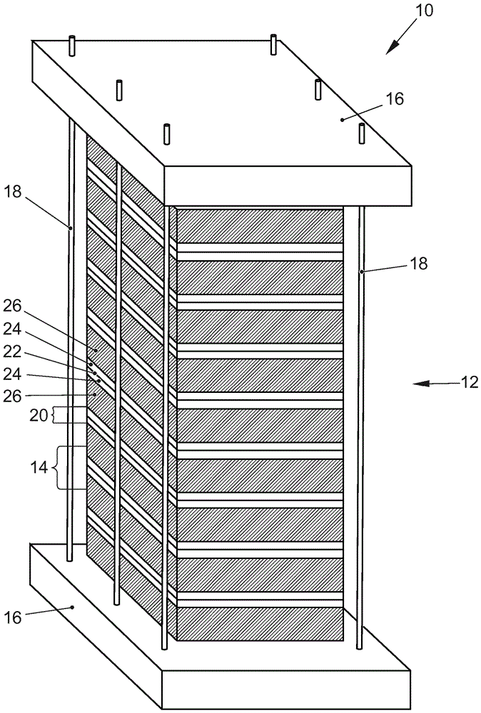
[0048] already explored figure 1 To explain the state of the art. The fuel cell according to the invention can basically have figure 1 configuration, however comprising a membrane electrode arrangement according to the present invention.

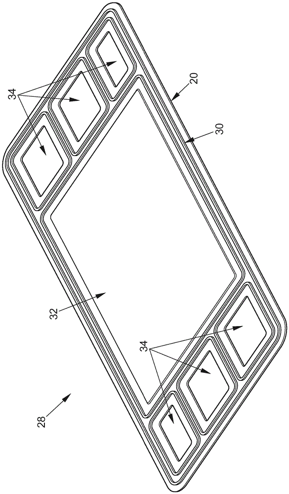
[0049] figure 2 A perspective view of the membrane electrode arrangement 28 according to the invention is shown in a preferred embodiment of the invention. The membrane electrode arrangement 28 includes a membrane electrode unit 20 (MEA) and a seal 30 . The membrane electrode unit 20 typically has a chemically active region 32 and can also have an opening 34 for passage of the operating medium.

[0050] The chemically active region 32 and the opening 34 for passage of the operating medium can, as shown, be jointly annularly surrounded by a seal 30 and be separated from one another once by this seal.

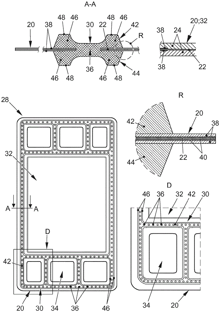
[0051] Next according to image 3 explain for constructing figure 2 Further details of the diaphragm electrode assembly 28 are shown ...


PUM


Abstract

The invention relates to a membrane electrode arrangement (28) for a fuel cell (10). The membrane electrode arrangement (28) includes a membrane electrode unit (20) and an integral seal (30) with a first sub-section (42) and a second sub-section (44). The diaphragm electrode unit (20) has a perforation (36) along which a seal (30) extends on both sides of the diaphragm electrode unit (20), wherein a first subsection (42) of the seal (30) is arranged on The second sub-section (44) is arranged on a first planar side of the diaphragm electrode unit (20) and the second sub-section (44) passes through the perforation ( 36) Connect to each other in one piece. Furthermore, the invention relates to a fuel cell (10) comprising a plurality of membrane electrode arrangements (28) according to the invention.

Description

technical field [0001] The invention relates to a membrane electrode arrangement for a fuel cell comprising a membrane electrode unit and a one-piece seal with two subsections. Furthermore, the invention relates to a fuel cell comprising a plurality of membrane electrode arrangements according to the invention. Background technique [0002] Fuel cells use the chemical conversion of fuel to water by oxygen in order to generate electricity. For this purpose, the fuel cell contains a so-called membrane electrode unit (MEA for membrane electrode element) as a core component, which is composed of an ion-conducting membrane, especially a proton-conducting membrane, and electrodes arranged on both sides of the membrane. (anode and cathode) composed of a composite structure. Furthermore, the membrane electrode unit can comprise gas diffusion layers which are generally arranged on both sides of the membrane electrode unit on the side of the electrode facing away from the membrane. ...

Claims


Application Information

Patent Timeline
Patent Type & Authority Patents(China)
IPC IPC(8): H01M8/1004H01M8/242H01M8/0276H01M8/0297H01M8/1007
CPCH01M8/0276H01M8/0297H01M8/1004H01M8/242H01M8/1007H01M8/0273Y02E60/50H01M8/0202
Inventor B.安德烈斯-肖特T.希克曼
Owner AUDI AG
Why Eureka
Try Eureka