Supercharge Your Innovation With Domain-Expert AI Agents!

Interface, communication apparatus, and program

A technology of interface and display device, which is applied in the direction of wireless communication, telephone communication, antenna support/installation device, etc., which can solve the problems of small communication area and inability to communicate, and achieve good communication effect

Active Publication Date: 2015-07-01
MURATA MFG CO LTD
View PDF10 Cites 12 Cited by
  • Summary
  • Abstract
  • Description
  • Claims
  • Application Information

AI Technical Summary

Problems solved by technology

[0004] However, if a cover made of silicone, for example, is attached to the communication terminal, the mark indicating the position of the antenna cannot be seen from the outside with the naked eye.
In addition, in the case where the case of the communication terminal is made of metal such as aluminum or stainless steel, there is a problem that the communicable area becomes small or communication becomes impossible

Method used


Image

  • Interface, communication apparatus, and program
  • Interface, communication apparatus, and program
  • Interface, communication apparatus, and program

Examples


Embodiment approach 1

[0073] Next, Embodiment 1 of the present invention will be described with reference to the drawings. In the description, for the sake of convenience, an XYZ coordinate system composed of mutually orthogonal X-axis, Y-axis, and Z-axis is used.

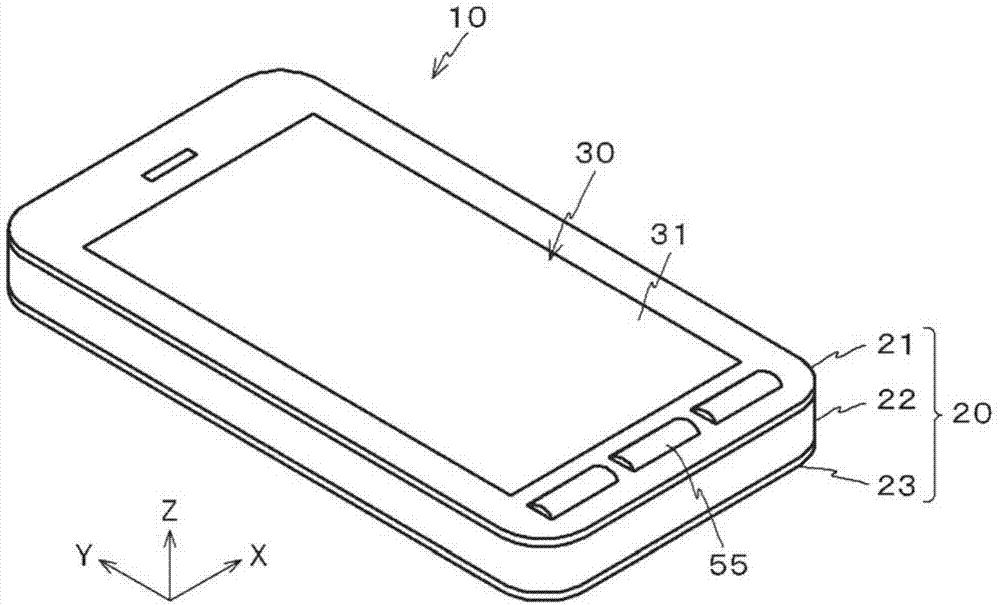
[0074] The communication terminal 10 of this embodiment is such as figure 1 Shown is a smartphone with interface 30 housed in housing 20 . The interface 30 is a graphical user interface using a touch panel.

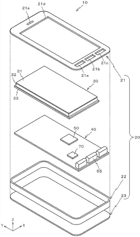
[0075] Such as figure 2 As shown, the communication terminal 10 has a front panel 21 , an outer frame 22 , and a rear panel 23 constituting a casing 20 , an interface 30 accommodated in the casing 20 , and a control board 40 .

[0076] The front panel 21 is a rectangular panel whose longitudinal direction is the Y-axis direction. A rectangular opening 21d through which the port 30 is exposed is formed in the front panel 21 . On the -Y side of the opening 21d formed in the front panel 21, rectangular openings 21a, 21b, and 21c...

Embodiment approach 2

[0119] Next, Embodiment 2 of the present invention will be described with reference to the drawings. In addition, for the same or equivalent configurations as in Embodiment 1, the same reference numerals are used.

[0120] Such as Figure 16 As shown, the interface 30A differs from the interface 30 according to the first embodiment in that the power supply coil 34 is located between the display 32 and the shielding plate 33 .

[0121] The feeding coil 34 according to the present embodiment has a square main body 340a including the coil pattern 34a, and a rectangular extension 340b extending from the main body 340a in the +Y direction. Since the extension part 340b has flexibility, it can be greatly deformed, such as bent. The body part 340 includes the coil pattern 34 a, and the extension part 340 b includes leads for connecting the coil pattern 34 a to the RFIC 70 provided on the control board 40 .

[0122] Such as Figure 16 As shown, the feeding coil 34 is arranged on t...


PUM


Abstract

A power supply coil is disposed on a rear surface of a display via a shield plate. When a current flows in the power supply coil, a magnetic flux emitted from the power supply coil traverses an opening of the shield plate. As a result, the power supply coil and the shield plate are electromagnetically coupled and the shield plate defines and functions as an antenna. Accordingly, a communication terminal communicates favorably with a smartcard, which is a device positioned on a front surface side of the display.

Description

technical field [0001] The present invention relates to an interface, a communication device, and a program. Background technique [0002] With the advancement of processors, communication terminals represented by mobile phones have functions equivalent to those of personal computers. In particular, a communication terminal equipped with a GUI (Graphical User Interface: Graphical User Interface) can provide a user with an interface corresponding to the purpose. Therefore, it is expected to be used for short-distance wireless communication based on the NFC (Near Field Communication: Near Field Communication) standard in addition to telephones. [0003] Conventionally, in order to perform short-range wireless communication, it was necessary to bring an antenna disposed on the rear side of a communication terminal close to an external device to be communicated. Therefore, a mark showing the position of the antenna is provided on the back of the communication terminal. [000...

Claims


Application Information

Patent Timeline
Patent Type & Authority Applications(China)
IPC IPC(8): H01Q7/00G06K19/07H01Q1/24H04M1/72412
CPCH01Q7/00H04M1/7253H04B5/02H04B5/0037H01Q1/243H04W88/06H04W4/008H04W4/80H04B5/79H04B5/24G06K19/07H01Q1/24H01Q1/526H04M1/72412H04B5/48
Inventor 中野信一三浦哲平加藤登
Owner MURATA MFG CO LTD
Features
  • R&D
  • Intellectual Property
  • Life Sciences
  • Materials
  • Tech Scout
  • Unparalleled Data Quality
  • Higher Quality Content
  • 60% Fewer Hallucinations
Learn More