Infrared heating device and drying furnace

A heating device and infrared technology, applied in the direction of heating to dry solid materials, electric heating devices, heating element materials, etc., can solve the problems of overheating, peeling off of the reflective film, deterioration of the reflective film, etc.

Inactive Publication Date: 2015-07-01
NGK INSULATORS LTD
View PDF6 Cites 5 Cited by
  • Summary
  • Abstract
  • Description
  • Claims
  • Application Information

AI Technical Summary

Problems solved by technology

[0006] However, in an infrared heating device having a structure in which a reflective film is provided on the surface of the inner tube of the double tube as in Patent Document 1, the reflective film may be overheated, thereby causing problems such as deterioration of the reflective film, peeling off, etc. and other bad situations

Method used


Image

  • Infrared heating device and drying furnace
  • Infrared heating device and drying furnace
  • Infrared heating device and drying furnace

Examples


Embodiment 1

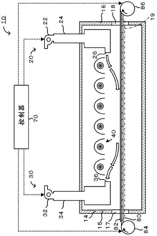
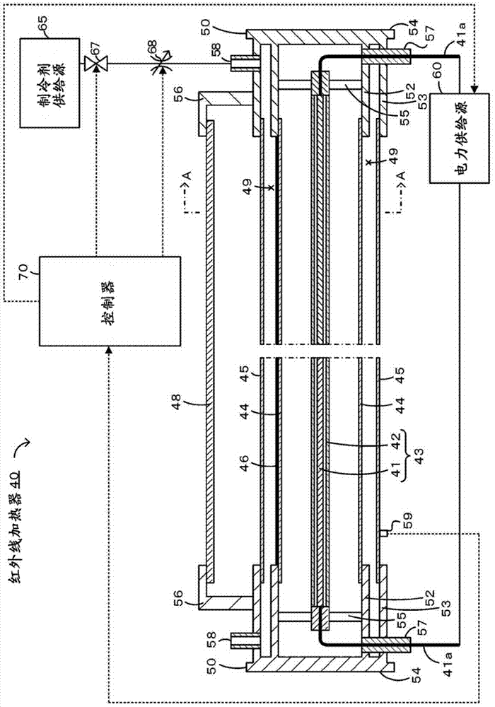
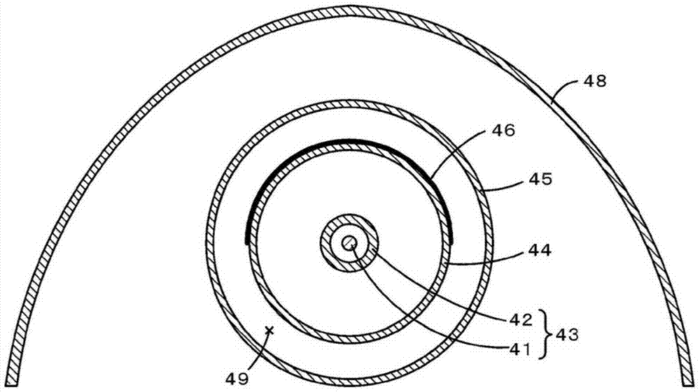
[0064] by Figure 1~3 The infrared heater 40 of the shown structure is Example 1. FIG. In addition, the outer diameter of the filament 41 of the heater main body 43 is 2mm, the material is tungsten, the heating length is 600mm, the material of the inner tube 42, the first outer tube 44, and the second outer tube 45 is quartz glass, and the material of the reflective layer 46 It is gold, and the film thickness is 5 μm. The reflector 48 is made of SUS304.

Embodiment 2

[0066] as Figure 8 As shown, except that the reflective layer 46 is not formed on the outer surface of the first outer tube 44 but is formed on the outer surface of the second outer tube 45 and the reflective layer 46 covers the upper half of the second outer tube 45 , the infrared heater having the same configuration as the infrared heater 40 of the first embodiment is the second embodiment.


PUM


Abstract

When electromagnetic waves containing infrared rays are released from a filament (41), the infrared rays are transmitted through an inner tube (42), the infrared rays reach a reflecting layer (46) provided at a distance from the inner tube (42) so as to cover only a part of the surroundings of the filament (41), and the infrared rays are reflected. At this time, the reflecting layer (46) is provided at a distance from the inner tube (42), and the reflecting layer (46) can be cooled by a coolant flowing through a coolant channel (49). It is thereby possible to suppress overheating of the reflecting layer (46) by a greater extent than when, e.g., the reflecting layer (46) is formed on the inner tube (42). A first outer tube (44) capable of transmitting infrared rays is provided between the inner tube (42) and the reflecting layer (46). The inner tube (42) and the first outer tube (44) are thereby present between the filament (41) and the reflecting layer (46), and overheating of the reflecting layer (46) can therefore be further suppressed.

Description

technical field [0001] The invention relates to an infrared heating device and a drying oven. Background technique [0002] Conventionally, as an infrared heating device such as an infrared heater that emits infrared rays, a device in which a heating element is enclosed in a tube such as a quartz tube is known. For example, Patent Document 1 describes a heating lamp in which a filament as a heating element is enclosed in a double tube of a quartz glass bulb and an outer tube, and a reflective film is provided on the outer periphery of the bulb as an inner tube. . In this heater lamp, the object to be heated can be efficiently heated by providing a reflective film on the outer periphery of the bulb in the direction opposite to the direction of the object to be heated. In addition, it is described that blackening of the bulb is suppressed by allowing cooling gas to flow between the bulb and the outer tube. [0003] prior art literature [0004] patent documents [0005] P...

Claims


Application Information

Patent Timeline
Patent Type & Authority Applications(China)
IPC IPC(8): H05B3/44F26B3/30H05B3/00H05B3/10
CPCF26B13/10F26B3/30H05B3/44
Inventor 藤田雄树
Owner NGK INSULATORS LTD
Why Eureka
Try Eureka