Microwave plasma abatement apparatus

A microwave plasma and plasma technology, applied in separation methods, gas treatment, dispersed particle separation, etc., can solve problems such as reducing device destruction efficiency and microwave generator damage.

Inactive Publication Date: 2009-01-07
EDWARDS LTD
View PDF1 Cites 3 Cited by
  • Summary
  • Abstract
  • Description
  • Claims
  • Application Information

AI Technical Summary

Problems solved by technology

[0014] The microwave radiation is reflected back towards the microwave generator, which may cause damage to the microwave generator; and
[0015] ●Changes in the impedance of the gas chamber, which may reduce the destruction efficiency of the device

Method used


Image

  • Microwave plasma abatement apparatus
  • Microwave plasma abatement apparatus

Examples


Embodiment Construction

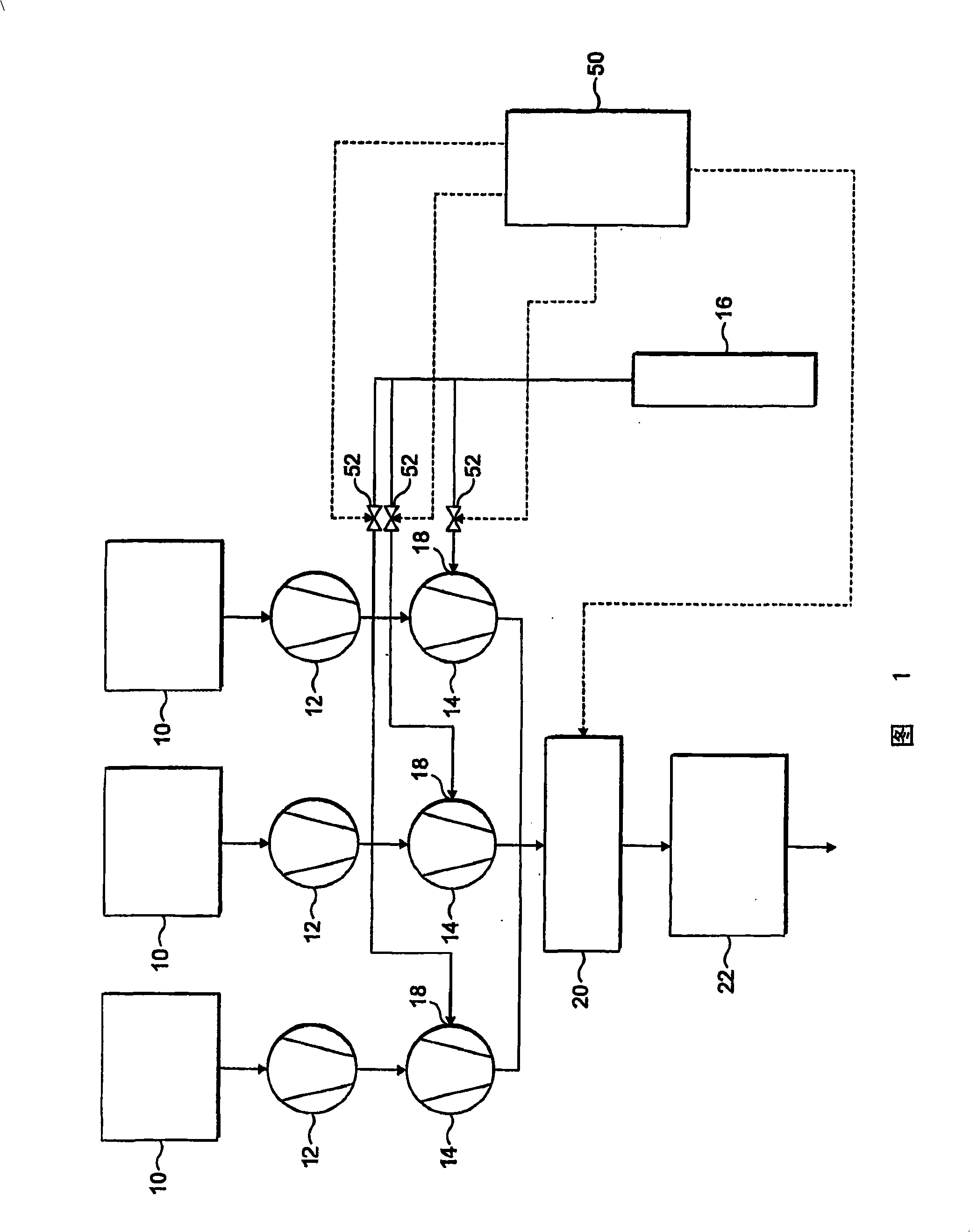
[0029] Referring first to FIG. 1, a processing tool includes a plurality of processing chambers 10, each for processing, for example, semiconductor devices, flat panel displays, or solar panel devices. Each processing chamber 10 receives various process gases for performing processing within the chamber 10 . For example, boron trichloride and chlorine may be provided for performing metal etch processes, ammonia and dichlorosilane may be provided for LPCVD processes, and sources of hydrogen bromide and chlorine for polysilicon etching. The process tool controls the supply of process gas to chamber 10 by providing control signals to valves and other flow control devices (not shown) for controlling the rate at which process gas is supplied to the chamber.

[0030] Exhaust gas is drawn from the outlet of each chamber 10 by a corresponding pump system. During processing within the chamber 10, only a portion of the process gas will be consumed, so the exhaust gas will contain a mix...


PUM


Abstract

In a method of operating a microwave plasma abatement apparatus comprising a microwave generator, and a gas chamber for receiving microwave energy from the microwave generator and within which a plasma is generated using the microwave energy, the amount of microwave energy that is not absorbed within the gas chamber is monitored, and the power of the microwave energy generated by the microwave generator is adjusted in dependence on the monitored microwave energy.

Description

technical field [0001] The present invention relates to a microwave plasma abatement device, and a method of operating such a device. The invention is particularly applicable to microwave plasma abatement apparatus for processing gas streams exhausted from a plurality of processing chambers. Background technique [0002] Various gases may be provided to the processing chamber during the formation of semiconductor or flat panel display devices in the chamber. During chemical vapor deposition, gases are supplied to a processing chamber containing a substrate and react to form a thin film on the surface of the substrate. For example, LPCVD (low pressure chemical vapor deposition) nitrogen processing uses DCS (dichlorosilane) and ammonia to form silicon nitride on the surface of the wafer. During the etch process, gases such as boron trichloride and chlorine may be supplied to the chamber to remove unwanted aluminum, and during the polysilicon etch process, hydrogen bromide an...

Claims


Application Information

Patent Timeline
Patent Type & Authority Applications(China)
IPC IPC(8): B01D53/00B01D53/32H01J37/32
CPCB01D53/007B01D53/32B01J19/126B01D2259/818B01D2259/806B01D53/00H01J37/32
Inventor M·拉多尤J·R·史密斯A·J·西利
Owner EDWARDS LTD
Why Eureka
Try Eureka