Master-slave burners for stove

A main burner and burner technology, applied in the direction of burners, gas fuel burners, and the combination of multiple burners, can solve problems such as durability deterioration, and achieve the purpose of preventing durability deterioration, suppressing overheating, Improve the effect of heat distribution

Inactive Publication Date: 2009-05-20
RINNAI CORP
View PDF1 Cites 4 Cited by
  • Summary
  • Abstract
  • Description
  • Claims
  • Application Information

AI Technical Summary

Problems solved by technology

Therefore, the head of the main burner is baked by the flame of the second main burner to reach a relatively high temperature, and the durability deteriorates.

Method used


Image

  • Master-slave burners for stove
  • Master-slave burners for stove

Examples


Embodiment Construction

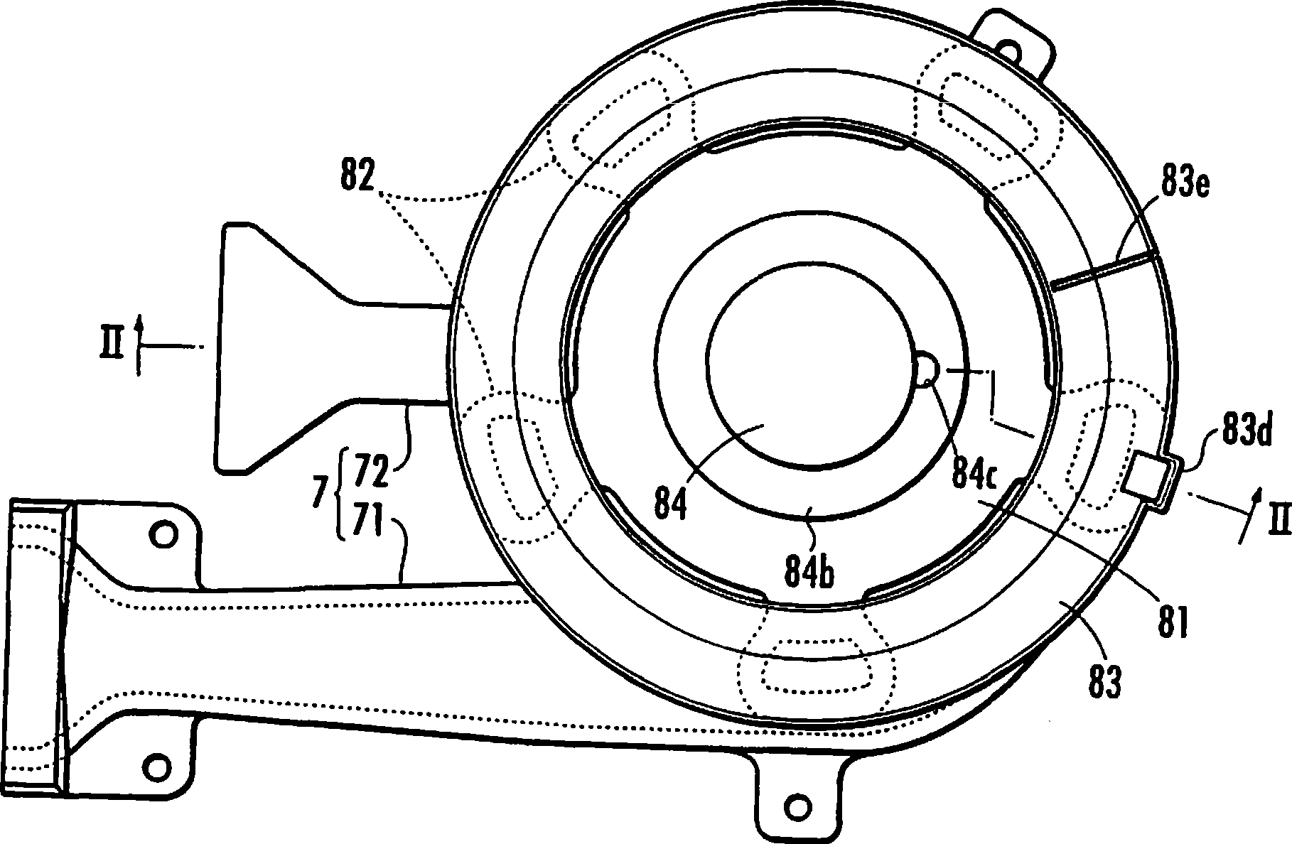
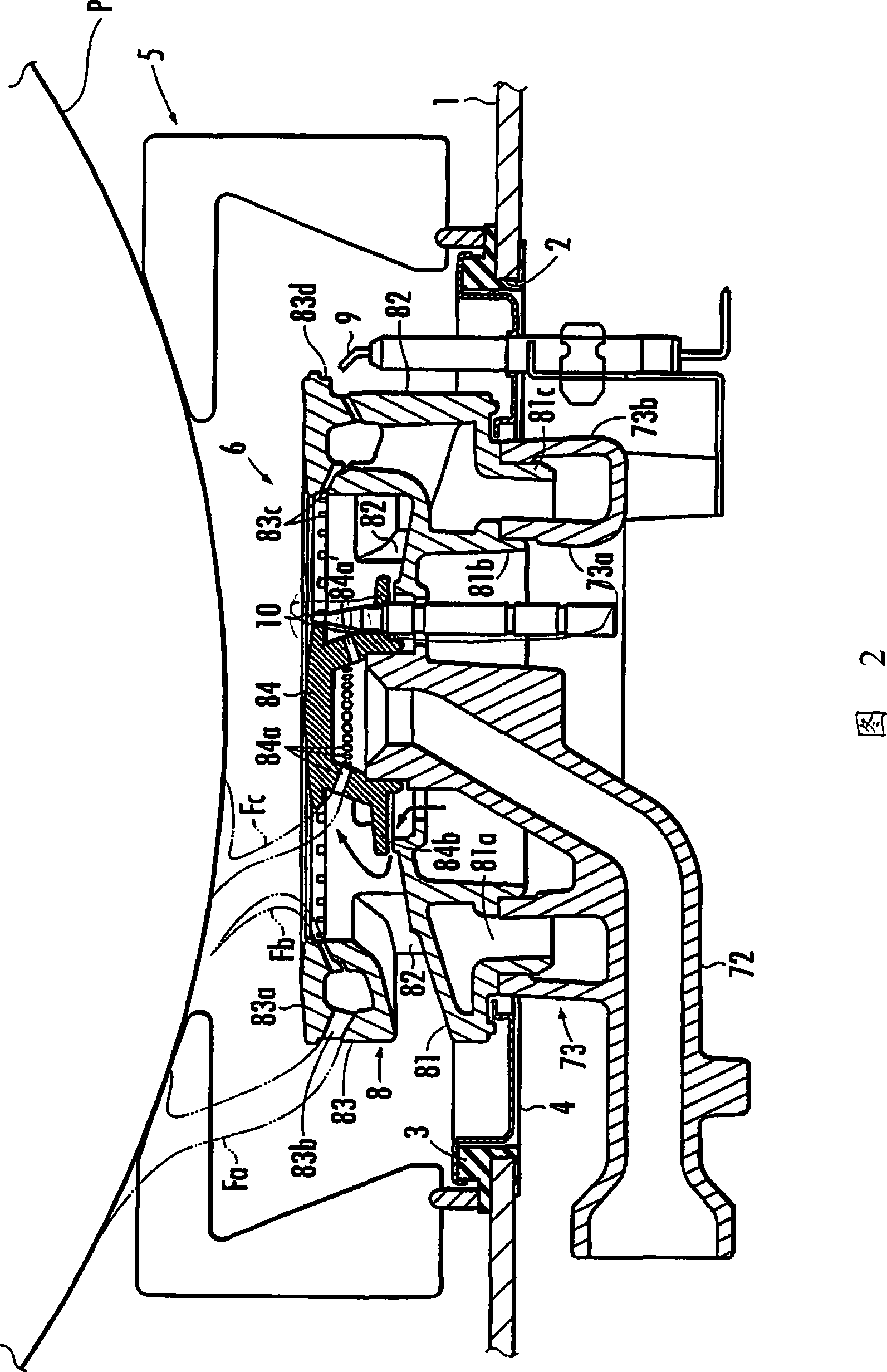
[0013] The embodiment of the present invention will be described with reference to FIG. 2. Reference numeral 1 is a top plate covering the upper surface of the stove main body, which is not shown in the figure. The top plate 1 is provided with an opening 2 for burners facing the main and auxiliary burners 6 of the embodiment of the present invention provided on the main body of the furnace. The top plate 1 is formed of a thick plate made of metal such as aluminum or a glass plate, and a gasket 3 is attached to the peripheral edge of the burner opening 2. In addition, the flame holder 5 and the annular juice tray 4 projecting into the burner opening 2 are placed on the gasket 3.

[0014] Such as figure 1 As shown in FIG. 2, the main and auxiliary combustor 6 includes a mixing tube unit 7 and a combustor main body 8. The mixing tube unit 7 has a first mixing tube 71 and a second mixing tube 72. At the downstream end of the first mixing pipe 71, a dispersion chamber portion 73 having...


PUM


Abstract

The invention provides a main and an auxiliary burner used on stoves. A first main burner glory hole (83b) is arranged at the periphery of the hollow annular main burner head (83) supported above a hollow basal disc (81) through a hollow pier piece (82). A barrel-shaped auxiliary burner head (84) is arranged in a space encircled by the main burner head; a side burner glory hole (84a) is arranged at the periphery of the auxiliary burner head to raise the heat distribution of the cooking vessel P as a heating object to the greatest extent, and to prevent the durability from declining caused by the overheat of the auxiliary burner head. A second main burner glory hole (83c) is arranged in the inside circumference of the main burner head. The auxiliary burner glory hole is set in a way that the upper end is arranged in a position no taller than the lower end of the second main burner glory hole.

Description

Technical field [0001] The invention relates to a main and auxiliary burner for a stove having a main burner head and an auxiliary burner head. Background technique [0002] Conventionally, as such a main and sub burner, the main and sub burner described in Patent Document 1 is known. The main and auxiliary burners have a burner main body that includes a hollow disc-shaped base portion connected to the first mixing pipe, and a plurality of pieces standing on the upper surface of the base portion at intervals in the circumferential direction. A hollow pillar portion, a hollow ring-shaped main burner head that is supported on the upper side of the base portion via the pillar portion and supplies mixed gas from the first mixing pipe via the inner space of the base portion and the inner space of the pillar portion . In addition, the main burner flame hole is provided on the outer circumference of the main burner head, and a tube connected to the second mixing tube and integrally form...

Claims


Application Information

Patent Timeline
Patent Type & Authority Applications(China)
IPC IPC(8): F23D23/00F23D14/02
Inventor 荒松政男
Owner RINNAI CORP
Why Eureka
Try Eureka