Water tank structure of electric steam box

A technology of electric steamer and water tank, which is applied in the direction of steam cooking utensils, cooking utensils, household utensils, etc. It can solve the problems of easy aging of sealing rings, hidden dangers of water leakage, and unreliable sealing, so as to avoid poor sealing and easy aging of sealing Effect

Inactive Publication Date: 2015-07-08
NINGBO FOTILE KITCHEN WARE CO LTD
View PDF9 Cites 5 Cited by
  • Summary
  • Abstract
  • Description
  • Claims
  • Application Information

AI Technical Summary

Problems solved by technology

The current embedded electric steamer generally uses a withdrawable water tank structure. This water tank structure has the advantages of convenient water filling and easy cleaning. However, due to the connection between the water tank and the water tank support, the plug-in silicone rubber sealing structure is currently used. The waterway is connected, so there is a hidden danger of water leakage caused by unreliable sealing or easy aging of the sealing ring
In addition, the inlet and outlet pipes and outlet pipes in the water tank structure of the existing electric steamer are all fixed structures, and there are also problems of unreliable sealing and hidden water leakage between the inlet and outlet pipes and the outer cover of the water tank. The specific water tank structure can be Reference patent No. ZL 201010228249.X (authorized announcement number is CN 101904685 B) disclosed in the Chinese invention patent "A water level warning prompt electric steamer water tank structure" and patent number ZL 201020260501.2 (authorized announcement number is CN 201727341 "A kind of electric steam box water tank structure with automatic replenishment" disclosed by the Chinese utility model patent of U)

Method used


Image

  • Water tank structure of electric steam box
  • Water tank structure of electric steam box
  • Water tank structure of electric steam box

Examples


Embodiment 1

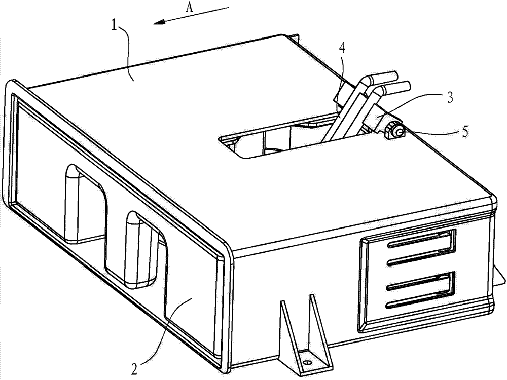
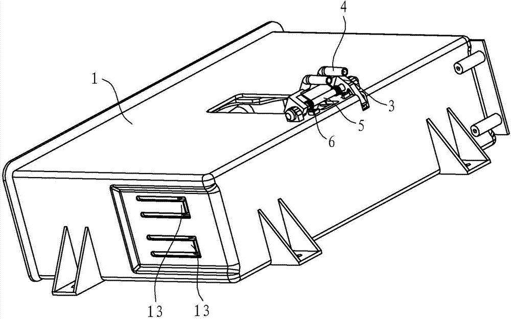
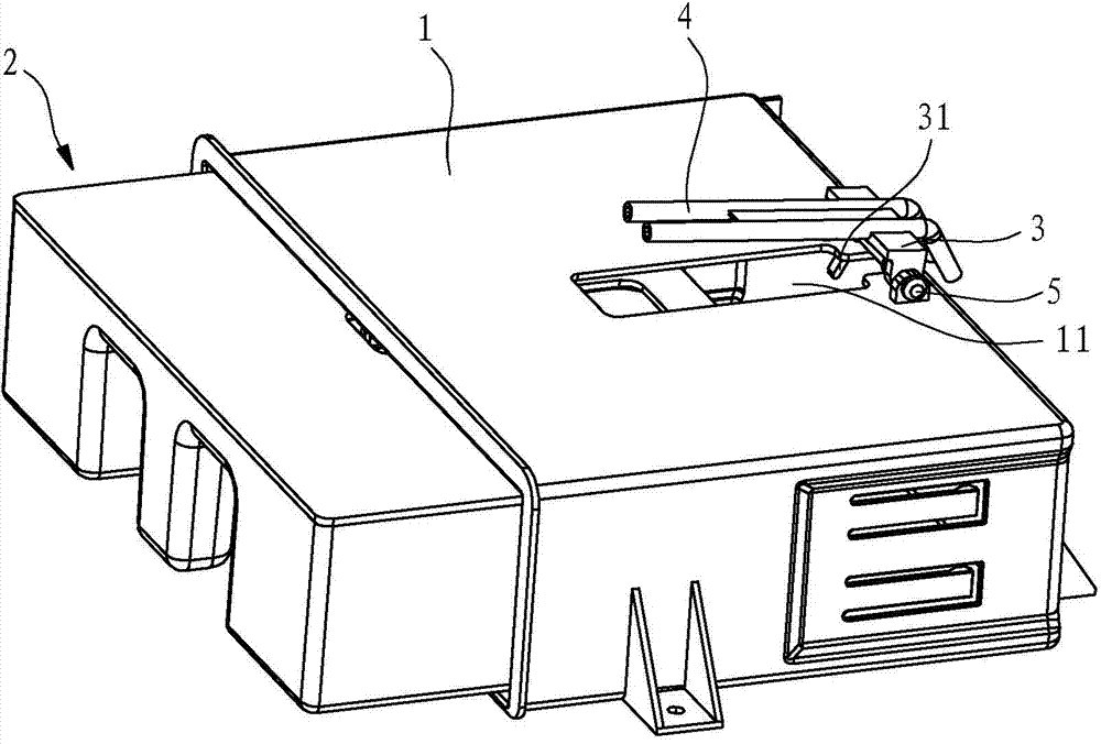
[0025] like Figure 1 to Figure 7 shown in figure 1 The direction indicated by the arrow A is forward. The water tank structure of the electric steamer in this embodiment includes a water tank support 1 and a water tank 2 mated with the water tank support. A fixed shaft 5 is installed above the rear side of the water tank support 1. On the fixed shaft 5, a swivel bracket 3 capable of rotating forward and backward is installed. The bottom of the swivel bracket 3 has a swing arm 31 extending forward and downward and capable of colliding with the back of the water tank and rotating. The swing arm 31 is integrated with the swivel bracket , the rear end of the water inlet and outlet pipe 4 is installed on the rotating bracket 3, and the water inlet and outlet pipe 4 is located above the swing arm 31 and rotates synchronously with the swing arm 31, and a torsion spring 6 is installed on the fixed shaft 5, and the torsion spring 6 One end of the torsion spring is fixed on the rotati...

Embodiment 2

[0034] like Figure 8 As shown, the water tank structure in this embodiment adopts an electric control method to rotate the water inlet and outlet pipes 4. Specifically, a micro switch 7 and an electric push rod 8 are installed on the water tank support 1, and the controller 9 is used to drive The electric push rod 8 stretches out or retracts, and the torsion spring is used to reset the rotated water inlet and outlet pipes 4 to the initial position.

[0035] The working principle of the water tank structure in this embodiment is as follows: when the water tank 2 is pushed into the water tank support 1, it is closed when the micro switch 7 is touched, which indicates that the water tank 2 has been pushed into place, and the controller 9 receives the signal and sends out The signal drives the electric push rod 8, so that the electric push rod 8 stretches out and the water inlet and outlet pipes 4 rotate counterclockwise, and the rotated water inlet and outlet pipes 4 extend into t...


PUM


Abstract

The invention discloses a water tank structure of an electric steam box. The water tank comprises a water tank support and a water tank matched with the water tank support in an insertion way. The water tank is characterized in that the water tank support is provided with a water inlet pipe and a water outlet pipe capable of rotating, the water inlet pipe and the water outlet pipe is rotated to obliquely protrude into the water tank from an initial position in the process of inserting the water tank into the water tank support or the status of inserting the water tank into the bottom of the water tank support under the function of a restoration piece, and the water inlet pipe and the water outlet pipe are reversely rotated and reset to be protrude into the water tank from the initial position from position when the water tank is inserted; when a complete machine stops working or needs to add water, the water inlet pipe and the water outlet pipe can be restored to the initial position, the pumping and returning of the complete machine can be realized in such a way that the rotary water inlet pipe and the water outlet pipe directly protrude into the water tank to be in contact with water, therefore the water inlet and outlet faults that the silica gel sealing structures of a traditional water tank and a water tank support water are not sealed and the sealing is likely to be aged and the hidden danger of leaking the waterway can be prevented.

Description

technical field [0001] The invention relates to a water tank, in particular to a water tank structure for an electric steamer. Background technique [0002] There are many types of water tank structures for electric steamers, among which the more common ones can be divided into extraction type water tank structure and external water tank structure with fixed water tank. The above two different water tank structures have their own advantages and disadvantages. The current embedded electric steamer generally uses a withdrawable water tank structure. This water tank structure has the advantages of convenient water filling and easy cleaning. However, due to the connection between the water tank and the water tank support, the plug-in silicone rubber sealing structure is currently used. To achieve waterway communication, there is a hidden danger of water leakage caused by unreliable sealing or easy aging of the sealing ring. In addition, the inlet and outlet pipes and outlet pip...

Claims


Application Information

Patent Timeline
Patent Type & Authority Applications(China)
IPC IPC(8): A47J27/04A47J36/00
Inventor 方小林曹骥茅忠群诸永定
Owner NINGBO FOTILE KITCHEN WARE CO LTD
Why Eureka
Try Eureka