
A food waste disposer

A technology for food waste treatment and grinding chamber, which is applied in grain processing, food science, electronic waste recycling, etc. It can solve problems such as electrical safety, motor burnout, motor burnout, etc., to avoid hidden dangers of water leakage, prolong service life, and ensure The effect of safe use

Inactive Publication Date: 2018-01-23
GREE ELECTRIC APPLIANCES INC
View PDF11 Cites 2 Cited by
  • Summary
  • Abstract
  • Description
  • Claims
  • Application Information

AI Technical Summary

Problems solved by technology

Ordinary families put leftover food residues, melon rinds, and fruit crumbs from every meal in plastic bags, and put them in a corner of the house, and take them outside when it is convenient. pollution, affecting the indoor environment
After washing vegetables and dishes, remove the leftovers from the sink and put them into garbage bags. Some of them will inevitably leak into the sewer and cause blockage, making cleaning more troublesome. At the same time, if the garbage bag leaks, the sewage will pollute the indoor floor etc.
[0003] Although the commonly used food waste disposers can efficiently dispose of the above food waste, such food waste disposers generally have a waterproof structure for the motor shaft, which adopts an oil seal and a shaft sleeve to dynamically seal the water at the motor shaft. This design structure has the hidden danger of water leakage due to the oil seal lip being easily worn after long-term operation. Once water leakage occurs, the motor will be burned and hidden dangers such as electrical safety are likely to occur, thus shortening the service life of the food waste disposer
[0004] In view of the above problems, a new food waste disposer is urgently needed to solve the problem that the waterproof structure of the existing food waste disposer is easy to wear, which may cause water leakage and burn the motor, and shorten the service life of the whole machine.

Method used


Image

  • A food waste disposer
  • A food waste disposer
  • A food waste disposer

Examples


Embodiment Construction

[0033] In order to make the technical problems solved by the present invention, the technical solutions adopted and the technical effects achieved clearer, the technical solutions of the embodiments of the present invention will be further described in detail below in conjunction with the accompanying drawings. Obviously, the described embodiments are only the technical solutions of the present invention. Some, but not all, embodiments. Based on the embodiments of the present invention, all other embodiments obtained by those skilled in the art without creative efforts fall within the protection scope of the present invention.

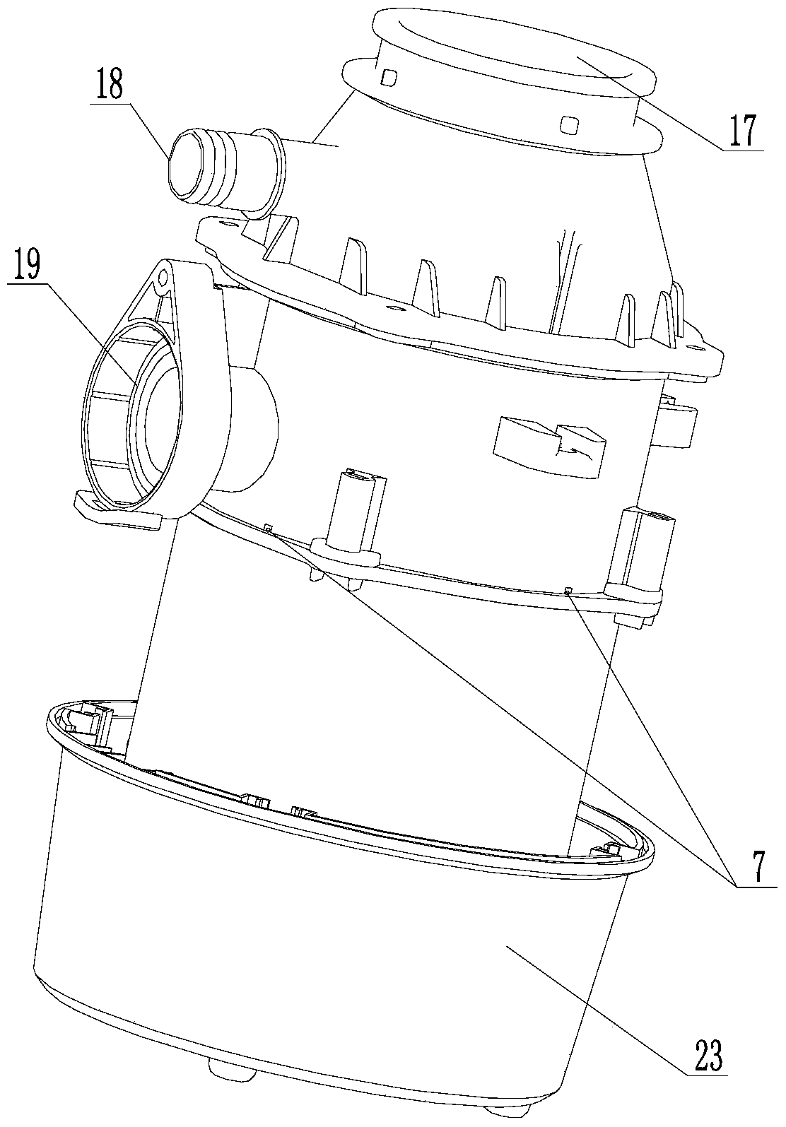
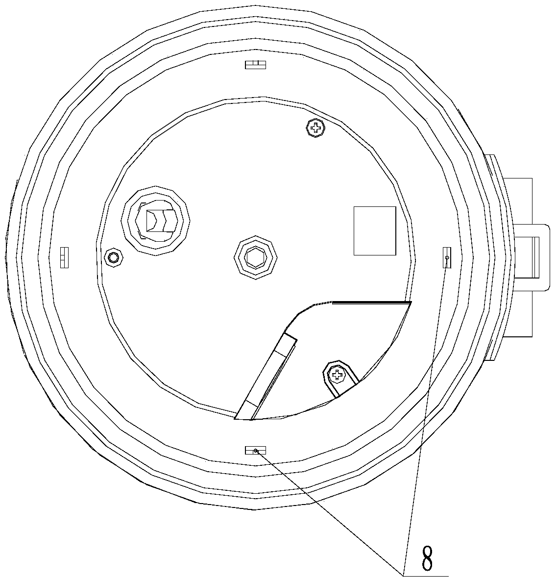
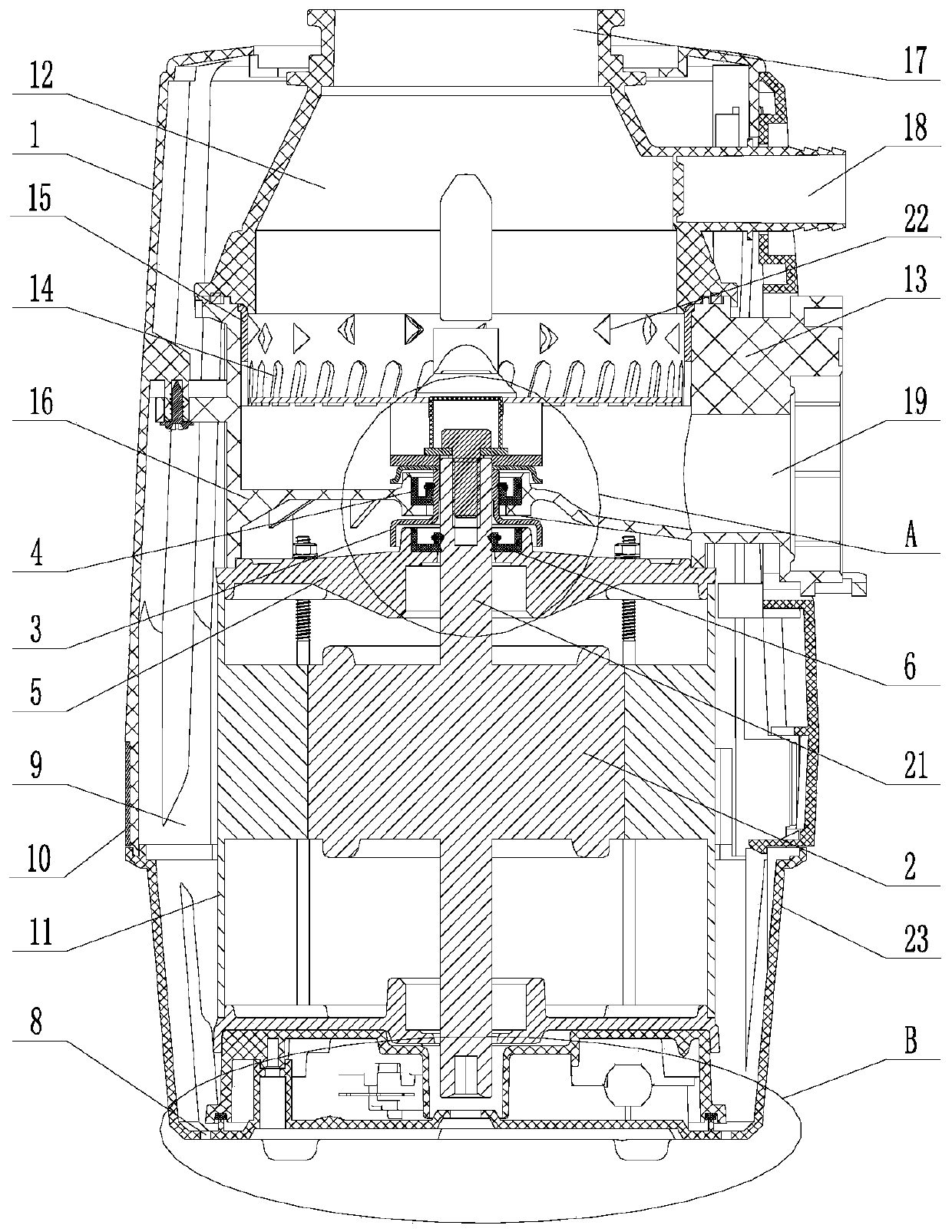
[0034] Figure 1 to Figure 6 A schematic structural diagram of the food waste disposer provided in this embodiment. Such as image 3 As shown, this embodiment proposes a preferred food waste disposer, which includes a casing 1 , a grinding chamber and a motor compartment 11 located in the casing 1 , and a first oil seal 4 . The motor 2 is installed ...


PUM


Abstract

The invention relates to the field of waste treatment equipment, and discloses a food waste disposer. The food waste disposer includes a shell, a grinding chamber and a motor compartment located in the shell, and the motor is installed in the motor compartment for outputting power to the grinding mechanism in the grinding chamber; it also includes a first oil seal for the motor shaft and the bottom of the grinding chamber The seal between the walls, the first oil seal is in interference fit with the shaft sleeve located outside the motor shaft; a through hole is opened on the bottom outer wall of the grinding chamber for draining the water leaked by the first oil seal. The present invention provides the first oil seal and the through hole for waterproofing and drainage, effectively avoiding the hidden danger of water leakage caused by the wear and tear of the lip of the oil seal, ensuring the safe use of electrical appliances, and prolonging the service life of the whole machine.

Description

technical field [0001] The invention relates to the field of waste disposal equipment, in particular to a food waste disposer with a waterproof structure. Background technique [0002] The disposal of food waste has always been a problem that the world attaches great importance to. Ordinary families put leftover food residues, melon rinds, and fruit crumbs from each meal in plastic bags, and put them in a corner of the house, and take them out when it is convenient. Pollution affects the indoor environment. After washing vegetables and dishes, remove the leftovers from the sink and put them into garbage bags. Some of them will inevitably leak into the sewer and cause blockage, making cleaning more troublesome. At the same time, if the garbage bag leaks, the sewage will pollute the indoor floor etc. [0003] Although the commonly used food waste disposers can efficiently dispose of the above food waste, such food waste disposers generally have a waterproof structure for th...

Claims


Application Information

Patent Timeline
Patent Type & Authority Patents(China)
IPC IPC(8): B02C7/00B02C7/11B02C23/04B09B3/00
CPCY02W30/82
Inventor 陈诗洁陈伟杰高静远谢武彬滕勇吴雄浩
Owner GREE ELECTRIC APPLIANCES INC
Learn More