Wheel component

A technology of wheel components and hubs, which is applied to vehicle parts, rims, transportation and packaging, etc. It can solve problems such as tire detachment, anti-detachment breakage, impact on fuel consumption, etc., to solve the problem of tire installation, increase rotational friction, The effect of preventing tire leaks

Inactive Publication Date: 2015-07-08
何晓艳
View PDF5 Cites 3 Cited by
  • Summary
  • Abstract
  • Description
  • Claims
  • Application Information

AI Technical Summary

Problems solved by technology

However, there are certain defects in this anti-off hub: 1. The installation process of the anti-off hub is relatively high. Whether the contact surface between the tire and the anti-off ring fits will directly affect whether the tire is leaking, and the installation process is cumbersome and complicated; When the vehicle runs at high speed or encounters a pothole, the temperature of the tire will rise and the tire pressure will rise, and the pressure on the tire is largely converted into the pressure on the anti-off ring. At this time, it is easy to cause the anti-off ring to break and cause the tire to break. The first is that the anti-off ring breaks and flies out, which may hurt the lives of others and cause property damage to others. Second, once the tire is off the ring, it will seriously affect

Method used


Image

  • Wheel component
  • Wheel component
  • Wheel component

Examples


Embodiment 1

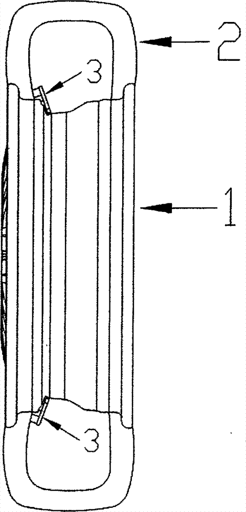
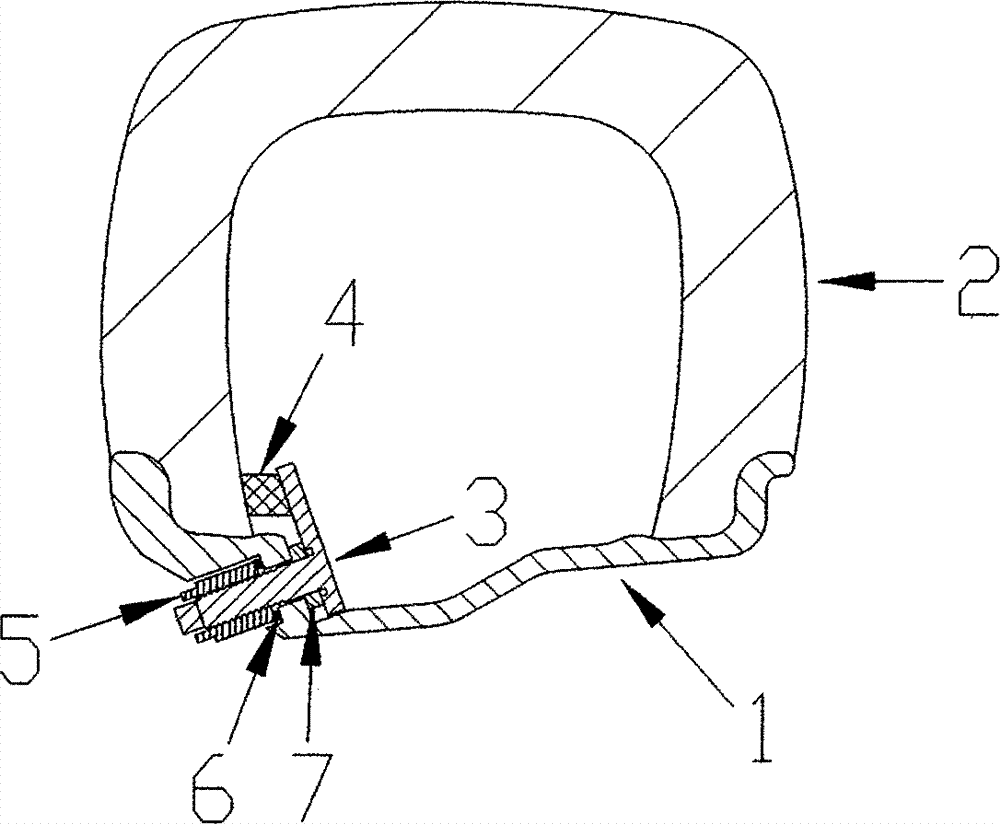
[0039] This embodiment provides a wheel assembly. like Figure 1-Figure 11 As shown, the wheel assembly includes an integral wheel hub 1 , a tire bead movable block 3 , a valve 12 , and a tire 2 . In addition to the round hole assembled with the valve 12, the integral wheel hub 1 also includes at least one round hole structure 14. There is a stop surface 15 around the round hole structure 14, and there is a hole at the intersection of the round hole structure 14 and the outer surface of the integral hub 1. The platform structure 13; the movable block 3 includes a rotating shaft 17 and a blocking plate structure 16, the blocking plate structure 16 is a cam structure, the rotating shaft 17 is located on one surface of the blocking plate structure 16, and the surface of the rotating shaft 17 has a threaded structure 18 , one end face of the rotating shaft 17 is a non-circular end face 19, and there is a groove structure 20 at the intersection of the rotating shaft 17 and the sto...

Embodiment 2

[0046] The difference between this embodiment and Embodiment 1 is that a tire bead movable block 3 is installed in at least one circular hole structure 14 on the side wall of the wheel groove 9 inside the two integral wheel hubs 1 rim bead seats, as Figure 12 .

Embodiment 3

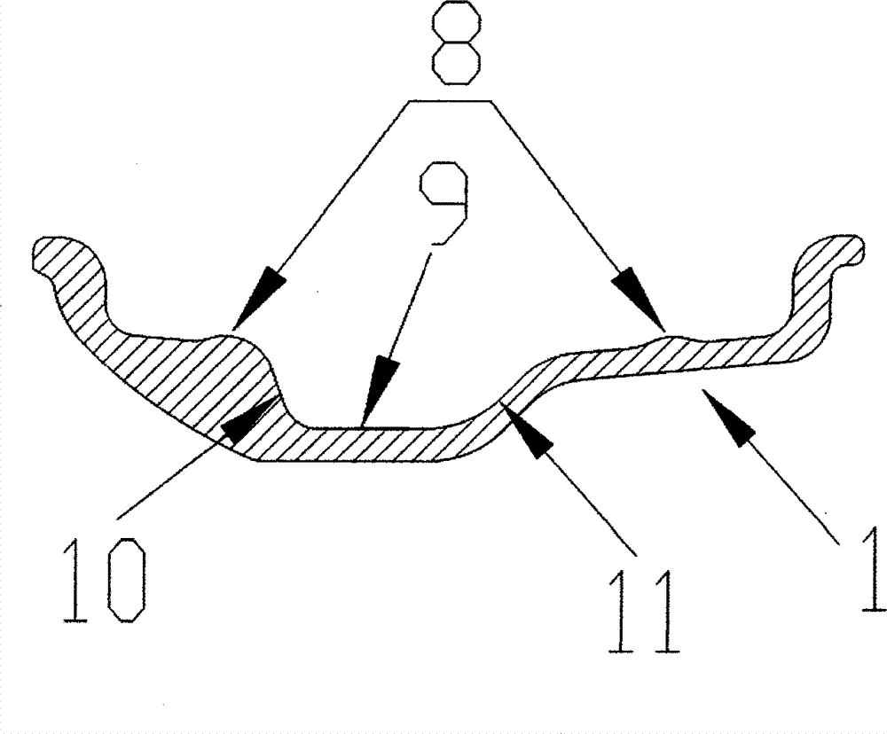
[0048] The difference between this embodiment and embodiment 1 is that the movable stopper 3 of the tire bead is in such as Figure 13 The position of a, by rotating clockwise to make the baffle structure 16 higher than the integral hub 1 rim bead seat protrusion 8 and not higher than the maximum shape of the hub (such as Figure 13 In b), block the tire bead 2 from sliding into the hub wheel groove 9.

[0049] See picture as Figure 13 In b, when the tire is low-pressure or zero-pressure and rotates counterclockwise, the stop surface 9 can prevent the tire bead movable block 3 from rotating clockwise again; Integral hub 1 appears to slide clockwise.

[0050] Or, in the circular hole structure adjacent to the same integral hub 1, tire bead movable stoppers 3 with the above two functions are alternately installed, thereby preventing the tire 2 from clockwise or counterclockwise with respect to the integral hub 1. slide.


PUM


Abstract

The invention discloses a wheel component. The wheel component comprises an integrated hub, a tire bead movable stop block, an inflating valve and a tire, wherein the tire bead movable stop block comprises a rotating shaft and a baffle plate structure, can move in the diameter direction of the integrated hub and can be mounted in a round hole structure in the side wall of a rim groove of the integrated hub in a sliding and/or rotating manner; the baffle plate structure is a cam structure and can rotate around the axis of the rotating shaft; and the tire is not provided with a tire tube. During tire installation, the tire bead movable stop block is not higher than a protruding peak of a hub rim bead seat, so that successful installation of the tire is guaranteed; after the tire bead is mounted on the bead seat of the integrated hub, the tire bead movable stop block slides and/or rotates to enable the baffle plate structure to be higher than the protruding peak of the hub rim bead seat so as to prevent the tire bead from sliding into the groove of the integrated hub; and the wheel component can prevent traffic accidents caused by disengagement of the tire and the hub, so that the driving security is improved.

Description

technical field [0001] The invention relates to an automobile accessory, in particular to a wheel assembly. Background technique [0002] When the vehicle is running, it is very dangerous for the tire to fall off the bead seat of the wheel hub and slide into the wheel groove. Once the tire falls off the bead seat of the wheel hub and slides into the wheel groove, it will cause the tire and the wheel hub to be out of sync. It is accomplished by controlling the wheel hub. After the tire is separated from the wheel bead seat, the steering and braking of the vehicle will be out of control, which may cause serious traffic accidents. When the vehicle is driving in the desert or off-road, we usually lower the tire pressure to increase the grip of the tire. When the vehicle tire is running at low pressure or 0 pressure (vehicle blowout), the tire is very easy to dislodge from the bead seat of the wheel hub. fall off. [0003] In order to prevent the tire from detaching from the be...

Claims


Application Information

Patent Timeline
IPC IPC(8): B60B21/12
Inventor 何晓艳
Owner 何晓艳
Why Eureka
Try Eureka