
An Electric Drive Hydraulic Independent Suspension Coiled Tubing Chassis

An independent suspension and electric drive technology, applied in suspension, elastic suspension, motor vehicles, etc., can solve problems such as inability to adapt to desert area operations, large turning diameter, and difficult turning, and achieve high off-road performance and ride comfort. Effects of increased usable space and small turning diameter

Active Publication Date: 2017-04-05
SANJIANG VOLAT SPECIAL VEHICLE
View PDF7 Cites 0 Cited by
  • Summary
  • Abstract
  • Description
  • Claims
  • Application Information

AI Technical Summary

Problems solved by technology

The whole vehicle cannot be equipped with other related bodywork equipment
Vehicle height is difficult to control
Poor off-road performance
Unsuitable for operations in desert areas
The minimum turning diameter of the whole vehicle is large, and it will be difficult to turn in case of sharp bends

Method used


Image

  • An Electric Drive Hydraulic Independent Suspension Coiled Tubing Chassis
  • An Electric Drive Hydraulic Independent Suspension Coiled Tubing Chassis
  • An Electric Drive Hydraulic Independent Suspension Coiled Tubing Chassis

Examples


Embodiment Construction

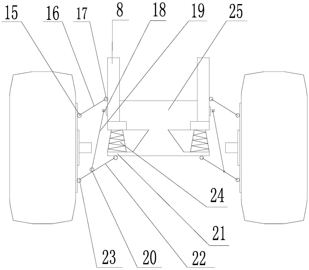
[0030] Such as Figure 1-2 As shown, an electrically driven hydraulic independent suspension coiled tubing chassis according to an embodiment of the present invention includes: a vehicle frame, which includes a longitudinal beam 8, a plurality of beams 28, a hollow frame beam 13 and a plurality of composite Crossbeam 25; the front end of the vehicle frame is equipped with a cab 1, the longitudinal beam 8 is connected with the hydraulic independent suspension system 9, and the hydraulic independent suspension system 9 is connected with the electric wheel 6, and the electric wheel 6 is installed There are tires 5; a generator set 2, a cooling system 3, and an exhaust system 4 are installed on the inner side of the front part of the vehicle frame; the generator set 2 includes an engine, a DC generator and an alternator; The power take-off 7 connected to the engine in the generator set 2, an electronic control system 11 and a braking system 12 are also installed on the vehicle fra...


PUM


Abstract

The invention provides an electrically-driven hydraulic independent suspension coiled tubing chassis. A generator set is provided with an engine, a DC generator and an AC generator. An independent suspension device comprises a first lower suspension arm base, and a hub is provided with a second lower suspension arm base. A lower suspension arm is mounted between the first lower suspension arm base and the second lower suspension arm base. A second dual-function hydraulic damping device base is arranged on the inner side of the lower suspension arm, and a first dual-function hydraulic damping device base is arranged on a longitudinal beam. A dual-function hydraulic damping device is mounted between the second dual-function hydraulic damping device base and the first dual-function hydraulic damping device base. The longitudinal beam is further provided with a first upper suspension arm base, and the hub is further provided with a second upper suspension arm base. An upper suspension arm is mounted between the first upper suspension arm base and the second upper suspension arm base. A clutch device, a gearbox, a transfer case and a transmission shaft are omitted, so that the actual using space is increased. Wheels bounce independently without affecting one another, so that independent steering is achieved. The electrically-driven hydraulic independent suspension coiled tubing chassis has the advantages of high off-road performance, smoothness and universality. An automatic tire inflating and deflating device can be additionally arranged.

Description

technical field [0001] The invention relates to an electrically driven hydraulic independent suspension coiled tubing chassis. Background technique [0002] The transmission system of the existing coiled tubing special vehicle chassis generally adopts the clutch device, gearbox, transmission shaft, and transfer axle. frame, and the transmission shaft is a universal joint rigid transmission shaft. The diameter of the tubing drum of the coiled tubing machine has various specifications according to the depth of the oil / gas well. For a well of more than 3,000 meters, the diameter of the tubing drum required is more than 3 meters. Therefore, a hollow frame is required for the chassis loaded with such rollers, and the rollers are partially sunk inside the frame and rigidly connected with the frame. [0003] At present, the chassis of the coiled tubing machine is limited by the composition of the transmission system, the space size and the structural form of the suspension system...

Claims


Application Information

Patent Timeline
Patent Type & Authority Patents(China)
IPC IPC(8): B60G13/08B60P3/00
Inventor 万勇
Owner SANJIANG VOLAT SPECIAL VEHICLE
Learn More