
Magnetically driven deviation self-adjustment belt type conveyer

A belt conveyor, magnetic drive technology, applied in the direction of conveyor, transportation and packaging, etc., can solve the problems of low conveyor belt conveyor efficiency, cost increase, low conveyor belt speed, etc., to prevent coal sprinkling and conveyor belt tearing , The effect of reducing thickness cost

Inactive Publication Date: 2015-07-08
CHINA COAL ZHANGJIAKOU COAL MINING MACHINERY
View PDF7 Cites 8 Cited by
  • Summary
  • Abstract
  • Description
  • Claims
  • Application Information

AI Technical Summary

Problems solved by technology

Ordinary belt conveyors rely on the friction of the driving roller to pull the conveyor belt to realize the continuous transportation of materials. During the transportation process, the thickness of the conveyor belt increases due to the large distance and large pulling force, and the cost increases.
Ordinary belt conveyors are driven by roller friction, so in order to prevent the conveyor belt from slipping, the conveyor belt speed is low, resulting in low conveyor efficiency
Ordinary belt conveyors are prone to conveyor belt deviation, resulting in spilled materials, polluting the environment, and risk of tearing the conveyor belt due to uneven force on the deviation conveyor belt

Method used


Image

  • Magnetically driven deviation self-adjustment belt type conveyer
  • Magnetically driven deviation self-adjustment belt type conveyer
  • Magnetically driven deviation self-adjustment belt type conveyer

Examples


Embodiment Construction

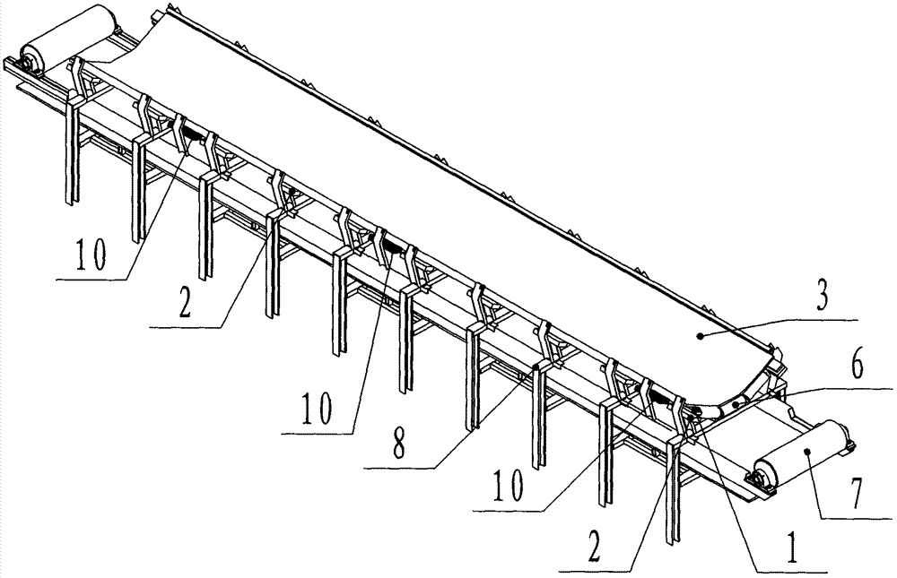
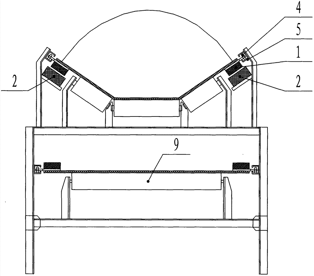
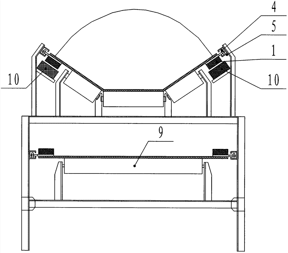
[0016] See attached figure 1 and attached figure 2 , a magnetically driven self-adjusting belt conveyor, including a permanent magnet array 1 (linear motor rotor), a linear motor stator 2, a conveyor belt 3, a guide roller 4, a guide groove 5, a load bearing roller assembly 6, and a reversing roller 7. Frame 8, return roller 9 and deflection adjustment magnet 10; the permanent magnet array 1 and the guide roller 4 are fixed on both edges of the surface of the conveyor belt 3 and arranged along the conveying direction of the conveyor belt 3; the straight line The motor stator 2 is installed on the frame 8 and arranged along the conveying direction of the conveyor belt 3; the guide groove 5 is installed on the frame 8, and the guide roller 4 moves in the guide groove 5 to support the conveyor belt 3 both sides; The carrying idler roller assembly 6 is installed on the top of the frame 8, and has the same structure as the common belt conveyor; the reversing roller 7 is installed...


PUM


Abstract

The invention belongs to the technical field of material conveying, in particular a magnetically driven deviation self-adjustment belt type conveyer. The magnetically driven deviation self-adjustment belt type conveyer is provided since a normal belt type conveyer has the disadvantages of increased cost of the conveying belt due to large hauling distance and large tension in a conveying process and has the risks of material scattering, environment pollution, conveying belt breakage and the like caused by deviation of the conveying belt in the conveying process. Specifically, a linear motor is adopted to drive the conveying belt, and magnetic force produced by electrifying a linear motor stator and magnetic force of a permanent magnet array coact to form driving force. The magnetic pole of a deviation adjustment magnet is the same as that of the permanent magnet array on the conveying belt; by means of repulsion force of permanent magnets, the deviation of the conveying belt in movement is adjusted. The conveyer has the beneficial effects that the concentrated force of single-point or multi-point rotary driving of the conventional conveying belt is uniformly distributed on the entire belt type conveyer, the cost of the conveying belt is reduced, and automatic deviation adjustment in operation of the conveying belt is realized by arranging the deviation adjustment magnet so as to prevent the problems of coal scattering and conveying belt breakage caused by deviation of the conveying belt.

Description

technical field [0001] The invention is designed in the field of transportation machinery, specifically a magnetically driven self-adjusting deflection belt conveyor. Background technique [0002] Belt conveyor is widely used in metallurgy, coal, transportation, hydropower, chemical industry and other departments because it has the advantages of large conveying capacity, simple structure, convenient maintenance, low cost and strong versatility. Ordinary belt conveyors rely on the friction of the driving roller to pull the conveyor belt to realize the continuous transportation of materials. During the transportation process, the thickness of the conveyor belt increases due to the large distance and high tension, and the cost increases. Ordinary belt conveyors are driven by roller friction, so in order to prevent the conveyor belt from slipping, the conveyor belt speed is low, resulting in low conveyor efficiency. Ordinary belt conveyors are prone to conveyor belt deviation, ...

Claims


Application Information

Patent Timeline
Patent Type & Authority Applications(China)
IPC IPC(8): B65G15/64B65G23/23
CPCB65G15/64B65G23/23
Inventor 王振刚马利任利范国杰王蕴博石欣欣李万宏
Owner CHINA COAL ZHANGJIAKOU COAL MINING MACHINERY
Learn More