
Turbine structure

A turbine and turbine blade technology, applied in the field of turbine structure, can solve the problems of high production cost, difficult maintenance, large gap, waste, etc., and achieve the effect of improving work efficiency and low energy loss

Inactive Publication Date: 2015-07-08
李宏生
View PDF0 Cites 5 Cited by
  • Summary
  • Abstract
  • Description
  • Claims
  • Application Information

AI Technical Summary

Problems solved by technology

Due to the large gap between the impingement water wheel and the lower part of the shell, the water rushes to the water wheel and falls into the lower drain port, causing water and other energy substances to flow away from the gap between the turbine blades and the shell, resulting in loss and waste of energy
[0003] Steam turbines are produced with densely packed blades, which are expensive and difficult to maintain. Steam flows between the blades, driving the rotor of the steam turbine to rotate, and steam travels between the blades, resulting in energy loss

Method used


Image

  • Turbine structure
  • Turbine structure

Examples


Embodiment 1

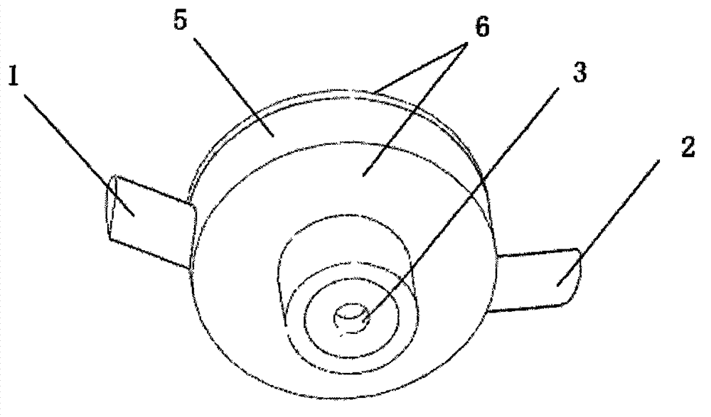
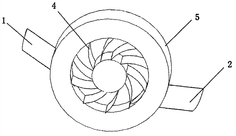
[0011] Such as figure 1 and figure 2 As shown, a turbine structure is composed of an annular casing 5 and two side end covers 6 to form a closed cavity, and a turbine blade 4 is installed inside the closed cavity, and the inner center of the turbine blade 4 is assembled with the rotating shaft 3 connection, the outer edge of the turbine blade 4 is rotated and attached to the inner wall of the annular casing 5 or the end covers 6 on both sides, and an energy inlet 1 is provided at one place on the closed cavity, and an energy inlet 1 is provided on the closed cavity. 1 is provided with an energy outlet 2 opposite to the other.

Embodiment 2

[0013] A turbine structure, a closed cavity is formed by an annular shell 5 and two side end covers 6, and a turbine blade 4 is installed inside the closed cavity, and the inner center of the turbine blade 4 is assembled and connected with the rotating shaft 3, and the turbine The outer edge of the blade 4 rotates and fits with the inner wall of the annular shell 5 and the end caps 6 on both sides. An energy inlet 1 is provided at one place on the closed cavity, and an energy inlet 1 is provided on the closed cavity opposite to the energy inlet 1. Another place is provided with energy outlet 2.

[0014] When working, water or steam enters the angular opening of the turbine blade from the energy inlet 1. Since the outer edge of the turbine blade 4 is in contact with the inner wall of the annular casing 5, the water or steam pushes the turbine blade 4 to rotate. When water or When the steam rotates to the energy outlet 2 along with the turbine blade 4, the water or steam is disc...


PUM


Abstract

The invention provides a turbine structure. An annular housing and end covers on the two sides are combined to form a closed chamber; a turbine blade is mounted inside the closed chamber; the inner center of the turbine blade is assembled and connected with a rotating shaft; the outer edge of the turbine blade is in rotating fit with the inner walls of the annular housing and the end covers on the two sides; an energy inlet is formed in the closed chamber at a position, while an energy outlet is formed in the closed chamber at another position opposite to the energy inlet. The turbine structure is of a closed structure, and as the inner wall of the annular housing of the turbine and the outer edge of the turbine blade are designed into close fit, while the turbine blade is designed into a free rotating structure, similar to a piston structure, water or vapor going into the turbine structure is capable of thoroughly driving the turbine blade to rotate without energy dissipation, and therefore, the acting efficiency of the water or the vapor is improved. The turbine structure is applicable to water turbines or steam turbines.

Description

technical field [0001] The invention relates to a turbine structure. Background technique [0002] There are two types of traditional water turbine turbine structures, one is counterattack type and the other is impact type. The impact type is that water flows away from between the blades to drive the water wheel to rotate; the impact type is that water impacts the water wheel. Due to the large gap between the impact water wheel and the lower part of the casing, the water rushes to the water wheel and falls into the lower drain, causing water and other energy substances to flow away from between the turbine blades and the casing, resulting in loss and waste of energy. [0003] Steam turbines are produced with densely packed fan blades, which are expensive to maintain and difficult to maintain. Steam flows from between the fan blades, driving the turbine rotor to rotate, and steam flows from between the fan blades, resulting in energy loss. Contents of the invention [000...

Claims


Application Information

Patent Timeline
IPC IPC(8): F03B3/00F01D1/06
CPCF01D25/24F03B11/02F05D2240/14Y02E10/20
Inventor 李宏生
Owner 李宏生
Features
  • Generate Ideas
  • Intellectual Property
  • Life Sciences
  • Materials
  • Tech Scout
  • Unparalleled Data Quality
  • Higher Quality Content
  • 60% Fewer Hallucinations
Learn More