
TLGF-HY-90-III type energy-saving material conveying fan

A technology of TLGF-HY-90-III, 1. TLGF-HY-90-III, applied to liquid fuel engines, parts of pumping devices for elastic fluids, mechanical equipment, etc., can solve the problem of high power consumption of wind turbines , affect the surrounding environment, non-compliance and other issues, to achieve the effect of less power efficiency, faster transmission process, and higher efficiency

Inactive Publication Date: 2015-07-08
ZHENJIANG DANTU DISTRICT FOOD FACTORY
View PDF5 Cites 1 Cited by
  • Summary
  • Abstract
  • Description
  • Claims
  • Application Information

AI Technical Summary

Problems solved by technology

[0004] The problem to be solved by the present invention is to provide TLGF-HY-90-Ⅲ energy-saving material conveying fan, which solves the fundamental purpose of low-carbon emission and energy saving that the existing fan has high power consumption and does not meet the national requirements, and at the same time has large noise and affects environmental problems

Method used


Image

  • TLGF-HY-90-III type energy-saving material conveying fan
  • TLGF-HY-90-III type energy-saving material conveying fan
  • TLGF-HY-90-III type energy-saving material conveying fan

Examples


Embodiment Construction

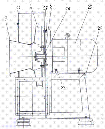
[0013] As shown in the figure, the TLGF-HY-90-Ⅲ energy-saving material conveying fan includes a frame 26, a casing 22, a motor 25, an impeller 1 and an air inlet ring 21, and the casing 22 is located above the frame 26 , the bottom of the motor 25 is fixed on the base 26 by bolts 27, the side of the motor 25 is fixedly connected to the casing 22 by bolts 27, and a sealing cover 23 is provided between the casing 22 and the motor 25, A dustproof cover 24 is provided on one side of the sealing cover 23 , the impeller 1 is arranged in the casing 22 , and the air inlet ring 21 is fixedly connected with the impeller 1 .

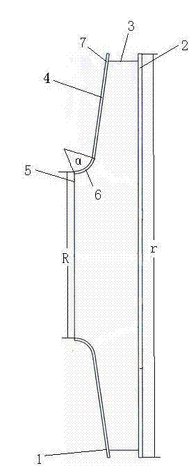
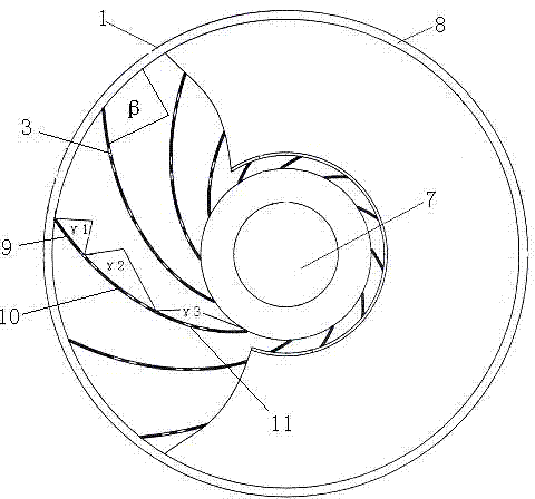
[0014] The above-mentioned TLGF-HY-90-III energy-saving material conveying fan, wherein, the impeller 1 includes a front disk 7, a rear disk 2 and blades 3, and the front disk 7 includes an expansion and contraction surface 4 and an air inlet 5. The expansion and contraction surface 4 and the air inlet 5 are connected into an integrated structure through a transiti...


PUM


Abstract

The invention provides a TLGF-HY-90-III type energy-saving material conveying fan. The material conveying fan comprises a stand, a shell, a motor, an impeller and an air inlet ring, wherein the shell is positioned on the upper side of the stand; the bottom of the motor is fixedly arranged on the stand through bolts; a sealing cover is arranged between the shell and the motor; a dust-proof cover is arranged on one side of the sealing cover; the impeller is arranged in the shell; the air inlet ring is fixedly connected with the impeller; the impeller comprises a front disc, a rear disc and a blade; the front disc comprises an expanding and shrinking surface and an air inlet; the expanding and shrinking surface and the air inlet are connected into an integrated structure through a transition component with a cambered section; the aperture of the air inlet and the aperture of the rear disc are R and r; one end of the blade is connected with the front disc, and the other end of the blade is tangential to the circle on the outer diameter of the impeller; the blade is formed by bending a single plate. The material conveying fan is rational in design, the electric energy efficiency is low, the fan operates stably under high-speed rotation, the noise is low, the purpose of environment protection is achieved, the efficiency of the fan is improved, the emission of carbon is reduced, and the purposes of energy conservation and cost reduction are achieved.

Description

technical field [0001] The invention relates to the technical field of material conveying fans. Background technique [0002] With the improvement of self-discovery and production technology, in the process of industrialization, there are more and more automation and assembly lines, and the use of fans to transport powder and granular materials is also more and more upgraded. Moreover, the process requirements for material transportation and the performance of the required fans vary widely. At present, there are considerable contradictions between market demand and the backwardness of material conveying fans, which are mainly reflected in three aspects: 1. The difference in required performance: the air volume and air pressure provided by the fan are related to the production process and process as well as the selected equipment and pipelines. Yes, fan products in the domestic and international markets only pay attention to the original fan design mode, but the process requ...

Claims


Application Information

Patent Timeline
Patent Type & Authority Applications(China)
IPC IPC(8): F04D25/08F04D29/28F04D29/66
Inventor 徐洋袁逸如王蓉蓉
Owner ZHENJIANG DANTU DISTRICT FOOD FACTORY
Learn More