
Movable LED backlight device

A backlight device and mobile technology, applied in lighting devices, fixed lighting devices, lighting auxiliary devices, etc., can solve problems such as inability to disperse, limited use of light source brightness for large-area panels, poor performance, etc., to reduce heat generation, The effect of reducing the number of LEDs and reducing power consumption

Inactive Publication Date: 2015-07-08
惠州德赛信息科技有限公司
View PDF10 Cites 9 Cited by
  • Summary
  • Abstract
  • Description
  • Claims
  • Application Information

AI Technical Summary

Problems solved by technology

However, it requires a light guide plate, and the application of light source luminance for large-area panels is limited, resulting in the inability to evenly disperse the light on the entire light guide plane.
[0005] From the above, it can be known that the two types of light sources currently on the market perform poorly in the case of large-area panels. In order to reduce the balance cost and improve the light source effect of large-area panels, a new backlight device must be proposed

Method used


Image

  • Movable LED backlight device
  • Movable LED backlight device
  • Movable LED backlight device

Examples


Embodiment Construction

[0020] A mobile LED backlight device of the present invention will be further described below with reference to the accompanying drawings.

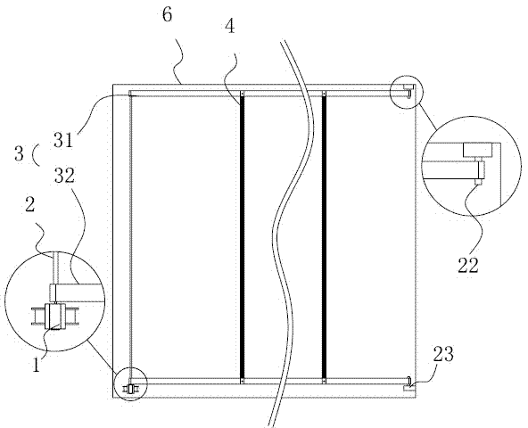
[0021] A mobile LED backlight device for providing backlight for display screens, such as figure 1 As shown, it includes: a motor 1, a rotating rod 2 connected to the rotor of the motor 1, a conveyor belt 3 driven by the rotating rod 2 through a linkage structure, at least one LED light bar 4 installed on the conveyor belt 3, and a For the housing 6 that accommodates and fixes the above components, the LED light bar 4 has two opposite light-emitting surfaces.

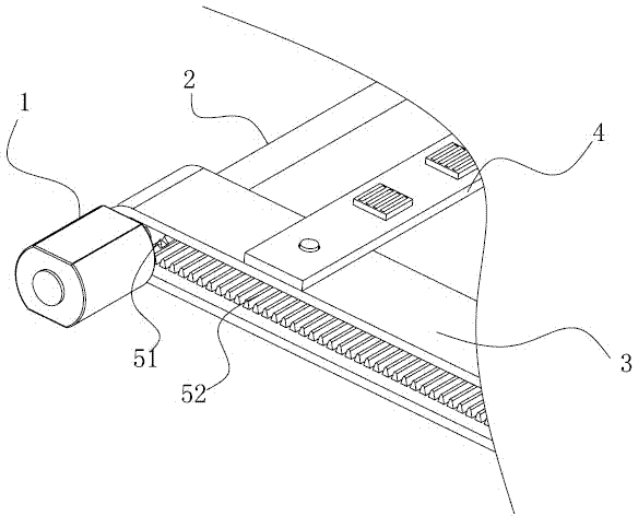
[0022] Specifically, such as figure 2 As shown, the motor 1 is a high-speed brushless motor, which can reduce the noise while ensuring the speed. The tail of the rotating rod 2 is directly connected to the rotor of the motor 1 or linked with the motor through a gear structure. When the rotor of the motor 1 rotates, the rotating rod 2 rotates accordingly, and the conveyor belt 3 ...


PUM


Abstract

The invention relates to a movable LED backlight device and used for providing backlight for a display screen. The movable LED backlight device comprises a motor, a rotating rod connected with the rotor of the motor, at least two annular conveyor belts parallel to each other and driven by the rotating rod to rotate, and at least one LED light bar bridged over the at least two annular conveyor belts; each LED light bar is provided with two opposite light exiting surfaces. The movable LED backlight device overcomes the problem of uneven light source of a large-area liquid crystal panel; compared with a down form, the number of LEDs is greatly reduced, the cost is reduced, and the electric energy consumption and the heating amount are reduced; compared with a side light form, a light guide plate is omitted so that the light source can be distributed more uniformly and the backlight of the large-area panel is effectively increased.

Description

technical field [0001] The invention relates to a backlight device, in particular to a mobile LED backlight device. Background technique [0002] At present, LED backlight technology is widely used in the field of liquid crystal display. There are mainly two types of light sources for LED backlight: direct-lit and side-lit; these two ways have their own advantages and disadvantages. [0003] The advantage of the direct type is that it does not require a light guide plate, and the uniformity of the light source is better when the light source is thick, but it requires a large number of LEDs, consumes a lot of power, and has a lot of ineffective heat, and the uniformity of the light source is poor when the light source is thin. When the LED is emitted at a large angle, due to the low light intensity in the middle, it is easy to cause dark spots and affect the uniformity of the backlight. [0004] In addition, the edge-lit type has the advantages of fewer LEDs required, more e...

Claims


Application Information

Patent Timeline
Patent Type & Authority Applications(China)
IPC IPC(8): F21S8/00F21V17/12F21V21/35F21V19/02F21V23/06G02F1/13357F21Y101/02F21K9/68F21Y115/10
CPCG02F1/133603G02F1/133608
Inventor 王德宇黄伟军黄伟烈
Owner 惠州德赛信息科技有限公司
Learn More