Absorption heat pump unit, heat exchanger unit and heat supply system

An absorption heat pump and heat exchange unit technology, applied in the field of heat exchange, can solve the problems of limited heat in the condenser, increased resistance of the primary network, and increased volume of the unit, so as to improve the overall thermal perfection and reduce the primary return water The effect of temperature

Inactive Publication Date: 2015-07-08
GREE ELECTRIC APPLIANCES INC
View PDF10 Cites 6 Cited by
  • Summary
  • Abstract
  • Description
  • Claims
  • Application Information

AI Technical Summary

Problems solved by technology

However, the pure absorption cycle and single-stage heat pump heat exchange unit can only reduce the return water temperature of the primary network to above 30 °C when the water supply temperature of the primary network is low (such as 100 ° C ~ 110 ° C). The cooling capacity of the return water is insufficient, and the heat recovered from the condenser at the heat source is limited
[0004] At p

Method used


Image

  • Absorption heat pump unit, heat exchanger unit and heat supply system
  • Absorption heat pump unit, heat exchanger unit and heat supply system
  • Absorption heat pump unit, heat exchanger unit and heat supply system

Examples


no. 1 Embodiment

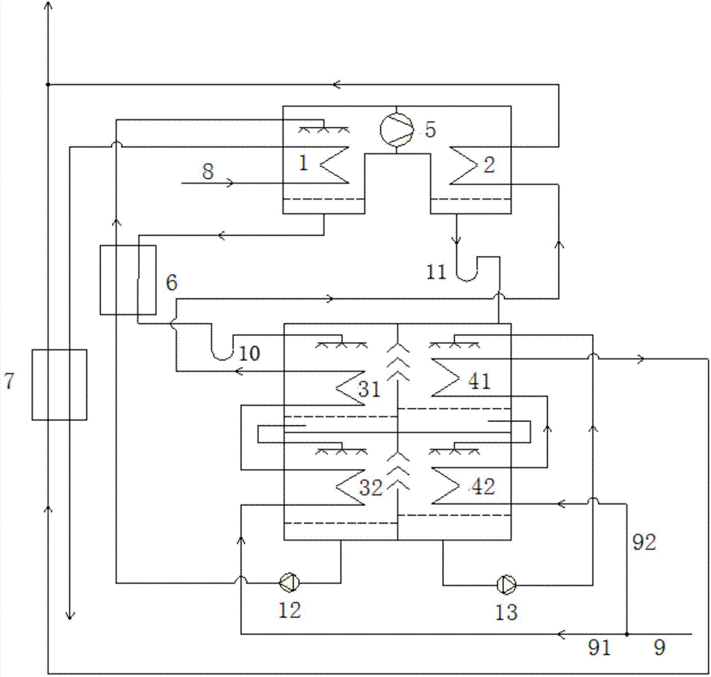
[0045] The first specific embodiment, a heat exchange unit with a water vapor compressor in the generation-condensation process:

[0046] like figure 2 As shown, it includes generator 1, condenser 2, first absorber 31, second absorber 32, first evaporator 41, second evaporator 42, water vapor compressor 5, solution heat exchanger 6, water- Water heat exchanger 7, solution circulation pump 12, refrigerant water circulation pump 13, solution pressure isolation device 10, refrigerant water pressure isolation device 11, etc.

[0047] For the circulation of external water: the primary water in the primary water inlet pipeline 8 first enters the generator 1 to generate a solution; after flowing out from the generator 1, it enters the high temperature side of the water-water heat exchanger 7 to heat part of the secondary water; After flowing out from the water-water heat exchanger 7, it returns to the heat source as primary effluent. The secondary water inlet pipeline 9 is divided...

no. 2 Embodiment

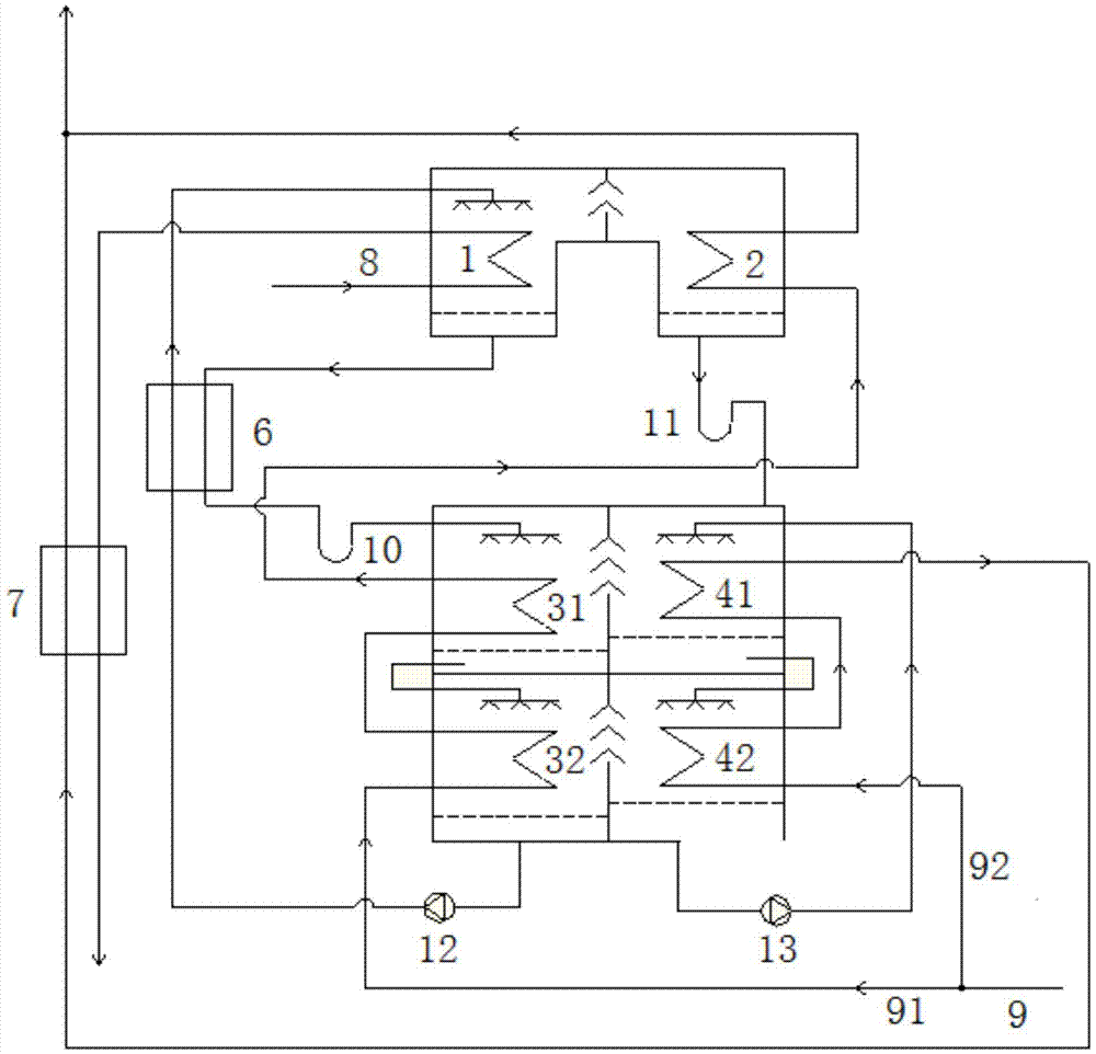
[0051] The second specific embodiment, the heat exchange unit of the anhydrous steam compressor in the generation-condensation process:

[0052] like image 3 As shown, it includes generator 1, condenser 2, first absorber 31, second absorber 32, first evaporator 41, second evaporator 42, solution heat exchanger 6, water-water heat exchanger 7, Solution circulation pump 12, refrigerant water circulation pump 13, solution pressure isolation device 10, refrigerant water pressure isolation device 11, etc.

[0053] For external water circulation: the primary water in the primary water inlet pipeline 8 first enters the generator 1 to generate a solution; after flowing out from the generator 1, it enters the high temperature side of the water-water heat exchanger 7 to heat part of the secondary water; - After the water heat exchanger 7 flows out, it returns to the heat source as the primary effluent; the secondary water inlet pipeline 9 is divided into two branches in parallel, wher...


PUM


Abstract

The invention relates to an absorption heat pump unit, a heat exchanger unit and a heat supply system. The absorption heat pump unit comprises a generator, a condenser, an absorber, an evaporator and a solution heat exchanger. The absorber at least comprises a first absorber body and a second absorber body, the evaporator at least comprises a first evaporator body and a second evaporator body, a solution outlet of the first absorber body is communicated with a solution inlet of the second absorber body, and a refrigerant water outlet of the first evaporator body is communicated with a refrigerant water inlet of the second evaporator body. The absorber bodies and the evaporator bodies are arranged, and therefore the overall heat power perfectness degree can be improved, and primary water return temperature can be lowered.

Description

technical field [0001] The invention relates to the technical field of heat exchange, in particular to an absorption heat pump unit, a heat exchange unit and a heating system. Background technique [0002] The application of cogeneration central heating system in urban heating in northern my country is very common. Lowering the return water temperature of the primary network of the central heating system is conducive to recovering the condensation heat at the heat source of the cogeneration for heating, which can greatly improve the efficiency of the cogeneration system. [0003] The heat supply system in the prior art has adopted a heat exchange unit with an absorption heat pump, and the heat exchange unit with an absorption heat pump can reduce the return water temperature of the primary network at each thermal station of the heat network. However, a simple absorption circulation, single-stage heat pump heat exchange unit can only reduce the return water temperature of th...

Claims


Application Information

Patent Timeline
IPC IPC(8): F25B15/06F24D3/18
CPCF24D3/18F24D2200/126F25B15/06F25B2315/007Y02A30/27Y02B30/62
Inventor 王升王娟陆超刘华张治平
Owner GREE ELECTRIC APPLIANCES INC
Why Eureka
Try Eureka