
Microseism interference imaging method

A technology of interference imaging and micro-seismic, applied in seismic signal processing, seismic signal receiver, etc., to overcome the influence, improve positioning accuracy, and broad application prospects

Active Publication Date: 2015-07-08
INST OF ACOUSTICS CHINESE ACAD OF SCI
View PDF2 Cites 15 Cited by
  • Summary
  • Abstract
  • Description
  • Claims
  • Application Information

AI Technical Summary

Problems solved by technology

[0004] Aiming at the problem that the conventional energy gathering or scanning method may be affected by the source mechanism in the processing of microseismic data, the present invention provides a microseismic interferometric imaging method for source location. By introducing the main event, the positioning resolution is improved, and Calculate the envelope of cross-correlation gathers containing travel time difference information to solve the problem of polarity changes in microseismic records, so as to improve the positioning accuracy of microseismic events and provide reliable basis and guidance for hydraulic fracturing fracture monitoring

Method used


Image

  • Microseism interference imaging method
  • Microseism interference imaging method
  • Microseism interference imaging method

Examples


Embodiment Construction

[0038] The technical solutions of the present invention will be described in further detail below with reference to the accompanying drawings and embodiments.

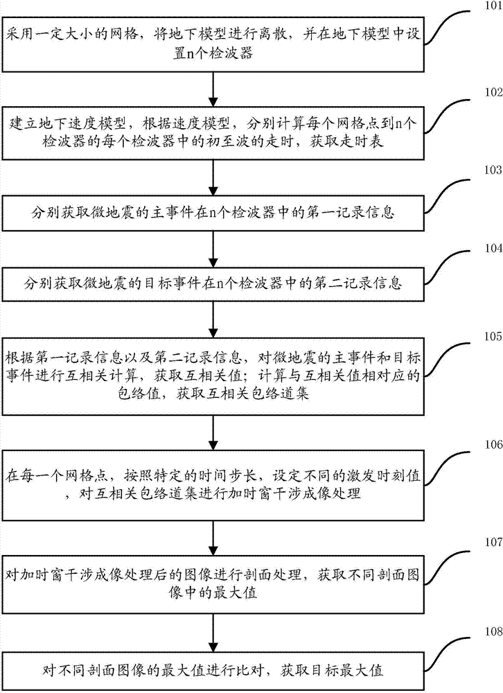
[0039] figure 1 It is a schematic flowchart of a microseismic interference imaging method provided by an embodiment of the present invention. Such as figure 1 As shown, the embodiment of the present invention specifically includes the following steps:

[0040] Step 101, discretize the subsurface model using a grid of a certain size, and set n geophones in the subsurface model.

[0041] Specifically, according to the actual situation of the underground target monitoring area, an underground model is established for the area to be monitored around the hydraulic fracturing, and the underground model is discretized by using a grid of a certain size. Moreover, in the underground model, n geophones are set at different positions according to certain rules. Wherein, the size of the grid is set according to actual needs, t...


PUM


Abstract

The invention relates to a microseism interference imaging method. The method includes the steps of dispersing an underground model through meshes of a certain size, arranging n detectors in the underground model, establishing an underground speed model, calculating the travel time between each mesh point and the preliminary wave of each detector according to the speed model, obtaining first record information of a main event of a microseism in the n detectors and second record information of a target event in the n detectors, conducting mutual correlation calculation on the main event and the target event of the microseism according to the first record information and the second record information, obtaining an envelope and a mutual correlation envelope gather, setting different trigger moment values at each mesh point according to the specific time step, conducting time-window-added interference imaging on the mutual correlation gather, conducting section processing on a processed image, obtaining the maximum values in different section images, comparing the maximum values of different section images, and obtaining the target maximum value.

Description

technical field [0001] The invention relates to the technical field of geophysical microseismic monitoring and positioning, in particular to a method for microseismic interference imaging. Background technique [0002] Hydraulic fracturing is one of the key technologies to achieve the economic development of unconventional oil and gas reservoirs. Microseismic monitoring technology is one of the most effective methods for real-time monitoring of hydraulic fracturing effects. By monitoring the weak earthquakes induced by hydraulic fracturing and other engineering operations, the spatial size and extension shape of fracturing fractures can be revealed, which helps to optimize the construction design and effect of fracturing. [0003] The traditional in-well microseismic positioning method requires first-arrival picking of effective events, but this method may have picking errors, resulting in positioning errors, and the efficiency is relatively low. Due to the extremely low s...

Claims


Application Information

Patent Timeline
Patent Type & Authority Applications(China)
IPC IPC(8): G01V1/28G01V1/20
Inventor 李磊陈浩王秀明
Owner INST OF ACOUSTICS CHINESE ACAD OF SCI
Learn More