
Plane lift-enhancing device high-velocity and high-velocity comprehensive optimum design method based on multiple subjects

A lift-increasing device and optimized design technology, applied in computing, special data processing applications, instruments, etc., can solve the problems of improving aircraft performance without considering the variable camber of the cruise wing, time-consuming, high cost, etc., to meet the high-speed cruise variable camber And the characteristics of low-speed take-off and landing, light weight, and the effect of meeting the requirements of trajectory kinematics

Active Publication Date: 2015-07-08
NORTHWESTERN POLYTECHNICAL UNIV
View PDF2 Cites 9 Cited by
  • Summary
  • Abstract
  • Description
  • Claims
  • Application Information

AI Technical Summary

Problems solved by technology

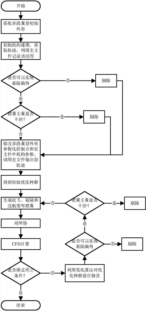
[0005] The purpose of the present invention is to solve the shortcomings of the existing high-lift device design process, such as long time-consuming and high cost caused by repeated design of mechanism and aerodynamics, and the lack of consideration of using the variable camber of the cruising wing to improve the performance of the aircraft. High and low speed comprehensive optimization design method of aircraft high-lift device

Method used


Image

  • Plane lift-enhancing device high-velocity and high-velocity comprehensive optimum design method based on multiple subjects
  • Plane lift-enhancing device high-velocity and high-velocity comprehensive optimum design method based on multiple subjects
  • Plane lift-enhancing device high-velocity and high-velocity comprehensive optimum design method based on multiple subjects

Examples


Embodiment Construction

[0031] Describe the present invention below in conjunction with specific embodiment:

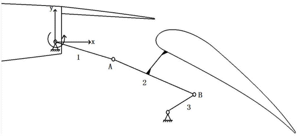
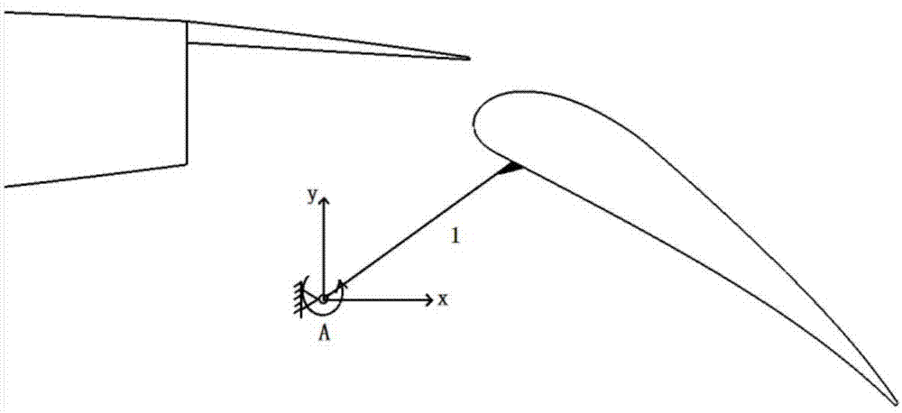
[0032] The high-lift device is generally composed of leading edge slats, main wings, and trailing edge flaps. At present, most of the leading edge slats of transport aircraft adopt the drive mechanism in the form of slide rails, and its motion trajectory is relatively simple, which is a typical arc trajectory. There are various forms of trailing edge flap drive mechanisms, among which the four-bar linkage mechanism, linkage slide rail mechanism and fixed-axis rotation mechanism are mostly used. The design of the trailing edge flap and its driving mechanism is a key part of the design of the high-lift device.

[0033] The present invention proposes a synchronous optimization method for the driving mechanism and aerodynamic performance of the high-lift device, and takes take-off performance, landing performance, cruise performance and mechanism element length information as optimization targe...


PUM


Abstract

The invention belongs to the field of plane design, and provides a plane lift-enhancing device high-velocity and high-velocity comprehensive optimum design method based on multiple subjects for solving the problems that in an existing lift-enhancing device design process, by means of a mechanism and pneumatic reciprocated iteration, consumed time is long, expenses are high, and plane performance can hardly be improved through a cruiser wing variable camber. Take-off performance, landing performance, cruising performance and the mechanism weight serve as optimization targets, parameterized control points of lift-enhancing device multi-section wing types, mechanism design parameters of the lift-enhancing device drive mechanism, required take-off configuration deflection angles, required landing configuration deflection angles and cruising stage variable camber deflection angles are optimized so that the configuration of the optimal comprehensive performance can be obtained. The method has the advantages that the requirement for the weight of the drive mechanism, the requirement for trajectory kinematics, the requirement for the high-velocity cruise variable camber and the requirement for low-velocity take-off and landing are all met while the system is optimized, and the method is suitable for various mechanism types, free of specific trajectory formulas and high in flexibility.

Description

technical field [0001] The invention belongs to the field of aircraft design, in particular to a multidisciplinary-based high-low-speed comprehensive optimization design method for an aircraft high-lift device. Background technique [0002] In recent years, the country has vigorously developed large-scale transport aircraft. As an important system of the aircraft, the high-lift device system has a very important impact on improving the safety and economy of the aircraft. For the current and future long-range wide-body passenger aircraft, using the high-lift device to realize the variable camber in the cruising stage is a new technology that can reduce resistance and reduce fuel consumption, which puts forward higher requirements for the design of the high-lift device. [0003] In the current design process of the high-lift device, the aerodynamic design and mechanism design are carried out separately according to different disciplines, and the use of the high-lift device to ...

Claims


Application Information

Patent Timeline
IPC IPC(8): G06F17/50
Inventor 白俊强刘睿沈广琛刘南邱亚松
Owner NORTHWESTERN POLYTECHNICAL UNIV
Learn More