Switching circuit with circuit protection function

A switching circuit and circuit protection technology, which is applied in the field of switching circuits with circuit protection functions, can solve problems such as circuit influence and control system work, and achieve the effect of preventing reverse current

Inactive Publication Date: 2015-07-08
CHENGDU LIXIN SCI & TECH
View PDF5 Cites 4 Cited by
  • Summary
  • Abstract
  • Description
  • Claims
  • Application Information

AI Technical Summary

Problems solved by technology

Once the switch circuit fails, it will affect the work of the control system
[0003] A common pro

Method used


Image

  • Switching circuit with circuit protection function

Examples


Example Embodiment

[0014] Hereinafter, the present invention will be further described in detail with reference to the embodiments and drawings, but the implementation of the present invention is not limited thereto.

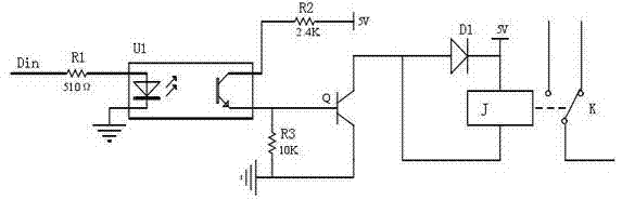
[0015] Such as figure 1 As shown, a switch circuit with circuit protection function includes a current-limiting resistor R1, a photocoupler U1, a resistor R2, a resistor R3, a transistor Q, a diode D1, and a relay; one end of the current-limiting resistor R1 is connected to an input signal Din, The other end is connected to an input end of the photocoupler U1; one input end of the photocoupler U1 is connected to the current limiting resistor R1, the other input end is grounded, and one output end is connected to the power supply Vcc through the resistor R2 (that is, one end of the resistor R2 is connected to the power supply VCC, The other end is connected to one output end of the photocoupler U1), the other output end is connected to the base of transistor Q; the collector of transi...


PUM

PropertyMeasurementUnit
Resistanceaaaaaaaaaa

Abstract

A switching circuit with the circuit protection function comprises a current-limiting resistor R1, a photoelectric coupler, a resistor R2, a resistor R3, a triode, a diode and a relay. One end of the current-limiting resistor R1 is connected with input signals and the other end of the current-limiting resistor R1 is connected with one input end of the photoelectric coupler. One input end of the photoelectric coupler is connected with the current-limiting resistor R1, the other input end of the photoelectric coupler is grounded, one output end of the photoelectric coupler is connected with a power source Vcc through the resistor R2, and the other output end of the photoelectric coupler is connected with the base electrode of the triode. The collector electrode of the triode is connected with the positive electrode of the diode, the emitting electrode of the triode is grounded, and the resistor R3 is further connected between the base electrode and the emitting electrode of the triode. The negative electrode of the diode is connected with the power source Vcc and a coil J of the relay is connected with the diode in parallel. The triode is adopted for controlling the relay to achieve the switching function, the reverse current is prevented through the photoelectric coupler, the circuit is protected, the switching circuit with the circuit protection function is obtained through less devices, and the circuit is easy to obtain and low in cost.

Description

technical field [0001] The invention relates to the field of switch circuits, in particular to a switch circuit with circuit protection function. Background technique [0002] The switch circuit is widely used in various automatic control systems and circuits, and plays an important role in the control system. The switch circuit is generally connected to the industrial computer or microprocessor of the control system, and is controlled by the industrial computer or microprocessor. The control of each loop plays a pivotal role. Once the switch circuit fails, it will affect the work of the control system. [0003] A common problem in current switching circuits is the generation of reverse currents that affect the circuit. Contents of the invention [0004] The object of the present invention is to overcome the shortcomings and deficiencies of the above-mentioned prior art, and provide a switch circuit with a circuit protection function capable of preventing reverse current...

Claims


Application Information

Patent Timeline
IPC IPC(8): H03K17/56H03K17/78H03K17/08
Inventor 赖金元
Owner CHENGDU LIXIN SCI & TECH
Why Eureka
Try Eureka