A Current Sampling Circuit Based on Bridge Circuit

A current sampling and bridge circuit technology, applied in the direction of measuring current/voltage, high-efficiency power electronic conversion, electrical components, etc., can solve the problem of being unable to distinguish the positive induced current circuit of the transformer, so as to protect the safety of the circuit and avoid the induced current , to ensure the effect of stability

Active Publication Date: 2021-09-24
HANGZHOU EV TECH CO LTD
View PDF5 Cites 0 Cited by
  • Summary
  • Abstract
  • Description
  • Claims
  • Application Information

AI Technical Summary

Problems solved by technology

[0005] The present invention mainly solves the problem that the sampling circuit in the prior art cannot distinguish the positive induced current of the transformer, which leads to abnormal operation of the circuit; it provides a current sampling circuit based on a bridge circuit, which can control the current sampling interval, thereby avoiding sampling to The transformer induces current to ensure the stability of the circuit operation

Method used


Image

  • A Current Sampling Circuit Based on Bridge Circuit
  • A Current Sampling Circuit Based on Bridge Circuit
  • A Current Sampling Circuit Based on Bridge Circuit

Examples


Embodiment 1

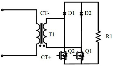
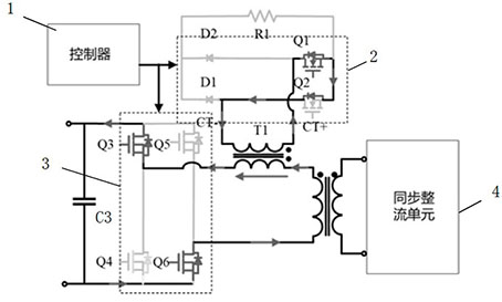
[0028] Embodiment 1: A current sampling circuit based on a bridge circuit, including a rectifier circuit 2, the rectifier circuit includes a first rectifier bridge arm formed by connecting a first switching tube Q1 and a second diode D2 in series, and a second switching tube Q2 The second rectification bridge arm is formed by connecting in series with the first diode D1, wherein the first rectification bridge arm and the second rectification bridge arm are connected in parallel, and the common node of the first switching tube and the second diode forms the first rectification bridge The midpoint of the arm, the common node of the second switch tube and the first diode forms the midpoint of the second rectifier bridge arm; the detection resistor unit (such as figure 1 The detection resistor R1 in the middle) is connected in parallel with the first rectifier bridge arm and the second rectifier bridge arm; the current transformer T1 includes a primary winding and a secondary windi...

Embodiment 2

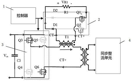
[0033] Embodiment 2, a current sampling circuit based on a bridge circuit. The difference between this embodiment and Embodiment 1 is that the primary winding of the current transformer T1 and the secondary winding of the current transformer T1 have different names. Connection, all the other structures are the same as in Embodiment 1. In this embodiment, when the controller controls the conduction of the MOS transistor Q3 and the MOS transistor Q6, it also controls the synchronous conduction of the MOS transistor Q2 (that is, the MOS transistor Q3, the MOS transistor Q6 and the Q2 receive the same control signal). When the secondary side synchronous rectification is turned on, the primary side circuit will flow an induced current (such as Figure 6 As shown by the middle arrow, it can also be called negative current), at this time, the primary current of the current transformer T1 flows in from the terminal with the same name, and the secondary current of the current transform...

Embodiment 3

[0036] Embodiment 3. In this embodiment, the end with the same name of the primary winding of the current transformer T1 is connected to the primary winding of the transformer, and the primary winding of the current transformer T1 is connected to the primary winding of the transformer and the second bridge arm of the full bridge circuit. Between the midpoints, the current transformer T1 is connected to the terminal with the same name, and the other circuit connection structures are the same as those in the first embodiment.


PUM


Abstract

The invention discloses a current sampling circuit based on a bridge circuit, which includes a first rectifier bridge arm formed by connecting a first switch tube and a second diode in series, and a bridge arm formed by connecting a second switch tube and the first diode in series. The second rectifier bridge arm, wherein the first rectifier bridge arm and the second rectifier bridge arm are connected in parallel, the common node of the first switch tube and the second diode forms the midpoint of the first rectifier bridge arm, the second switch tube and the second rectifier bridge arm The common node of a diode forms the midpoint of the second rectifying bridge arm; the detection resistance unit is connected in parallel with the first rectifying bridge arm and the second rectifying bridge arm; the present invention controls the bridge unit and the rectifying circuit through a peak current controller The switch tube is controlled to prevent the reverse current problem on the primary side of the transformer caused by the synchronous rectification of the secondary side, effectively protect the circuit safety, and control the current sampling interval, so as to avoid sampling the negative current of the transformer and ensure the circuit work stability.

Description

technical field [0001] The invention relates to the technical field of power electronics, in particular to a current sampling circuit based on a bridge circuit. Background technique [0002] With the explosive growth of new energy vehicles, the demand for on-board chargers and on-board DC-DC has also increased significantly. Due to the wide voltage range of vehicle power batteries and low-voltage batteries, bridge DC-DC circuits that can simultaneously realize wide-range input and wide-range output have been widely used. The control or protection of the bridge circuit needs to rely on the accurate sampling of the current waveform on the primary side of the transformer. Using the current transformer CT for sampling can achieve high precision, low delay, and low cost, so it has been widely used. [0003] However, when the bridge circuit uses synchronous rectification, since the secondary side synchronous rectification is turned on, the reverse current will appear on the prima...

Claims


Application Information

Patent Timeline
Patent Type & Authority Patents(China)
IPC IPC(8): H02M1/00G01R19/00H02M1/088H02M1/32H02M3/335
CPCH02M1/00H02M1/088H02M1/32H02M3/33592Y02B70/10H02M7/219H02M3/33571H02M3/33573H02M1/0009
Inventor 徐晨汀陶斯力贺强平定钢
Owner HANGZHOU EV TECH CO LTD
Why Eureka
Try Eureka